
Gravure Cross-Web Density Variation

When one gravure color prints lighter at both edges, darker through the center, weak on one side, or shows a fixed band across the web, the first useful clue is where that density difference sits across the width. Measure the same image area at fixed positions from left to right and keep the print unit, substrate roll, line speed, and impression setting with the sample.

Then watch what the pattern follows. If it stays with one print unit, keep checking ink transfer, the gravure cylinder, doctoring, and that unit’s impression condition. If it follows a substrate roll, look at the material. If the same weak or heavy area stays at the same machine-width position through those comparisons and reacts repeatedly to impression changes, the impression roll and cross-web contact distribution deserve a closer look.

For roller positions used around gravure impression contact and web handling, Printing Industry Rollers provides the broader application background.

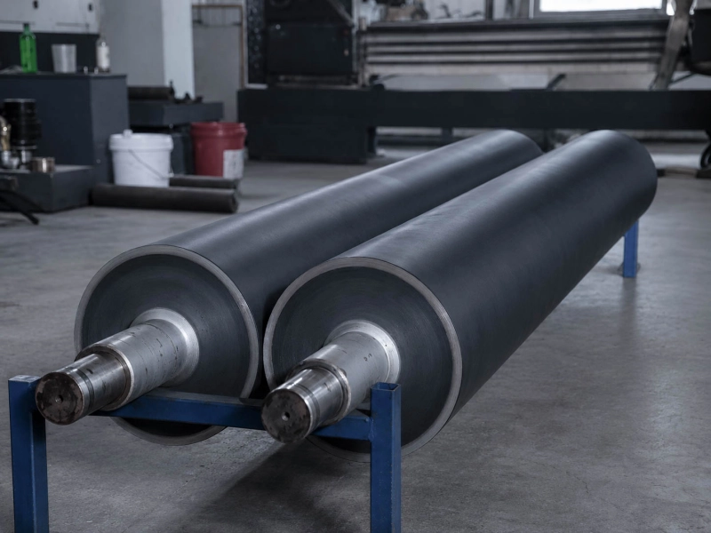
Black rubber coating rollers with machined steel shaft ends

Map the Density from Left Edge to Right Edge

“Light at the edge” describes what the operator sees, but it is still too broad for troubleshooting. Fix the measurement positions before changing the press. Left, center, and right are a practical starting point. If a visible band sits between them, add readings inside the band and immediately beside it.

Use the same solid, tonal patch, or repeatable image area at every position. Take the readings close together in time. If the left side is measured on a solid and the right side on another tonal area several minutes later, normal changes in ink condition can distort the comparison.

A Simple Cross-Web Record

Where to measure What to record Keep with the sample
Left side Density or gray value and distance from the reference edge Print unit and color
Center Density or gray value Substrate type, thickness, roll or lot
Right side Density or gray value and position across the web Line speed and impression setting
Visible band Reading inside the band and readings beside it Web width and sampling time

The individual numbers matter less than the shape they form. For example, left / center / right readings of 1.42 / 1.51 / 1.43 form a roughly symmetric center-heavy profile. Readings of 1.40 / 1.48 / 1.50 show a different problem because density is rising toward one side. These figures are only examples of profile shape; the approved print target for the actual job remains the quality reference.

Keep using the same measurement positions during later trials. A fixed band is much easier to trace when its position is always recorded from the same reference edge.

Read the Shape Before Changing the Impression Roll

Both Edges Are Light and the Center Is Darker

When both edges are lighter by a similar amount, compare other colors on the same substrate first.

If several print units show a similar edge-to-center shape, inspect conditions shared by those units. Cross-web differences in substrate thickness, compressibility, coating, treatment, or surface condition can change how evenly the material enters impression contact.

If only one color shows the problem, stay with that unit. Ink condition and circulation, the gravure cylinder, doctor blade contact, contamination, and the unit’s impression condition are more useful checks at this stage.

When those comparisons leave the same symmetric profile in place and impression adjustment repeatedly makes the center-to-edge difference stronger or weaker, the loaded profile of the impression roll becomes more relevant.

One Side Stays Lighter

For a one-sided problem, track the weak side through each controlled change.

If changing the substrate roll moves or removes the weak side, inspect the material profile. Thickness, coating, treatment, and compressibility can vary across the width even when two rolls carry the same nominal specification.

If several substrate rolls give the same result on one print unit, move back to that unit. Check the cylinder, doctoring, ink delivery, and lateral impression condition.

If different substrates and different cylinders still leave the operator side or drive side consistently weak, the machine-side geometry deserves attention. Parallelism, loading at the two ends, bearings, shaft support, and the impression roll then belong in the same mechanical check.

A Band Stays at the Same Width Position

A fixed band gives you an exact axial position to follow. Record its distance from one reference edge.

Suppose a darker band stays 300 mm from the operator-side edge after a substrate change and remains at the same position after changing the gravure cylinder. The fixed position is now more useful than the description “pressure band.” It tells you where to inspect the contact system.

Useful checks at that axial position include local outside diameter, cover condition, hardness consistency, grinding profile, loading, and nearby mechanical support.

If the band moves with another substrate roll, stay with the material. If it disappears with another cylinder or print job, continue on the print-unit side.

Scattered missing dots belong to another gravure-transfer problem. Gravure Missing Dots: Ink Transfer Checks covers that defect separately.

If a mark repeats at a regular pitch along the machine direction rather than staying in one cross-web position, compare the repeat distance with rotating components. Why Repeat Marks Appear on Web Materials covers that pattern.

See What Makes the Profile Move or Change

During a trial, change one useful production variable and keep the others as steady as the job allows. Then measure the same width positions again.

What the profile follows Check next A stronger signal
One print unit or color Ink condition, cylinder, doctoring, and unit contact Other colors remain relatively even on the same substrate
One substrate roll or lot Thickness, coating, treatment, compressibility, and surface profile Several colors develop a similar shape on the same material
Line speed Ink transfer and drying first; dynamic contact if the position remains fixed The same profile returns at the same speed condition
Impression setting Cross-web contact distribution The same width positions repeatedly become lighter or darker
Same machine-width position Roller geometry, local cover condition, loading, and support The position remains after substrate and cylinder changes

Changing pressure, ink viscosity, speed, and substrate during the same trial often removes the evidence you need. A better print does not tell you much if four conditions changed at once.

Impression pressure is particularly easy to misread. Increasing pressure may improve a weak area, but watch the whole width. If the weak edge improves while the center becomes noticeably heavier, the response itself is useful evidence about cross-web contact distribution.

If the print changes mainly with ESA operation, keep that on the electrical transfer-assist path. It should not be used by itself to judge roller crown or mechanical loading.

When the Impression Roll Is Worth Measuring in Detail

The impression roll becomes a strong lead when the density difference stays at the same machine-width position, sensible ink/cylinder/substrate comparisons do not move it, and changing impression load repeatedly changes the same part of the profile.

For the general requirements of controlled nip contact, see Pressure Rollers. On a wide gravure impression roll, the following measurements give a much clearer picture than one nominal diameter and one hardness value.

Compare the Loaded Shape with the Printed Profile

A long impression roll can be within its unloaded dimensional specification and still produce a different contact shape under pressure. Shaft stiffness, roll-body stiffness, working face length, cover compression, bearing support, and loading at the two ends all affect the loaded profile.

Crown changes that profile as well. An existing crown may have worked with a previous load or substrate and become less suitable after operating conditions change. Regrinding and wear can also alter the original profile.

When an older impression roll ran the same job well, compare its known profile and working condition with the current roll before deciding on a new crown direction. For the wider design question, see Crowned Rubber Rollers: When Crown Matters.

Measure Diameter at the Positions That Matter

Measure across the face rather than taking one reading at the center. Left, center, and right give a basic profile. If the print has a fixed band, add measurements at that axial position and on both sides of it.

For a band recorded 300 mm from the operator side, measure the roller around that same 300 mm position. This direct position-to-position comparison is much more useful than collecting extra measurements at unrelated locations.

Repeated grinding, local wear, contamination, or surface damage can leave a small axial diameter difference. On a wide and pressure-sensitive nip, a difference that looks minor on the roller can still show up clearly in the printed density profile.

Compare Hardness Across the Working Face

If a density band keeps returning at one axial position, one nominal hardness value is not enough to describe the cover. Where the inspection method allows, compare hardness at several positions under similar roller and temperature conditions.

A local hard or soft area changes compression at that point. Uneven ageing, glazing, swelling, chemical exposure, local wear, or previous repair can create this type of difference even when the roller still looks acceptable from a distance.

The useful comparison is cross-web consistency against the proven working specification. A universal hardness number cannot replace that comparison.

For a One-Sided Problem, Check Both Ends

When only one side of the print stays weak, check the impression roll as part of the complete supported assembly. Parallelism, bearings, shaft support, and loading at the operator and drive sides can all influence the lateral contact profile.

A new rubber cover cannot correct an angular nip or unequal loading at the two ends. If those conditions remain unchanged, replacing the cover alone may leave the same one-sided density problem in place.

Where the press has an approved nip or contact-print check, compare the left, center, and right under the same setup. The result becomes especially useful when a low-contact area lines up with the weak position already recorded in the density profile.

Keep These Details with the Impression Roll

If the investigation reaches the impression roll, keep the information that describes the roller itself and the conditions around its contact: drawing if available, face length, shaft and core dimensions, outside-diameter readings across the face, existing crown information, available hardness readings, and clear photos of the old cover.

Add the exact roller position, substrate thickness, line speed, impression condition, and the media that regularly reach the cover during production or cleaning. Keep the cross-web density profile with the roller records, including the position of any fixed band.

If the previous impression roll ran the same job well, its dimensions, hardness, surface condition, crown, and service history provide a useful manufacturing reference. A straightforward replacement with a proven drawing and working specification can usually move forward without turning the project into a lengthy troubleshooting exercise.

When the same cross-web density problem has returned after replacement or regrinding, keep the old failure pattern with the new project. Copying the nominal diameter and hardness alone can reproduce a contact profile that was already causing trouble.

More on Gravure Impression Rollers and Materials

Printing Industry Rollers

Roller positions and working conditions around printing, impression contact, and web handling.

Pressure Rollers

Roller design considerations for nip contact, pressure distribution, geometry, and full-width contact stability.

NBR / Nitrile Rubber Rollers

A material direction for selected printing positions involving compatible ink, oil, cleaning media, or other industrial liquid contact.

Polyurethane Rubber Rollers

A material direction for roller positions where wear resistance, load support, and repeated mechanical contact are stronger requirements.

If you already have drawings, dimensions, samples, or a clear impression-roll specification, send them to Wolorin for custom manufacturing, quotation, or production confirmation.

If details are incomplete, start with old roller photos, basic dimensions, roller position, contact medium, and the current roller-related density problem.