Gravure Missing Dots and Incomplete Ink Transfer

Gravure missing dots can begin at several points in the transfer process. A blocked cell carries little or no usable ink. Ink in a shallow cell may dry or empty too early. A rough substrate may leave tiny gaps at the printing nip.

Start with the defect itself, then follow the transfer path:

engraved cell → ink release → substrate surface → impression contact

Dots that repeat at the same image position usually keep the check near the gravure cylinder. A weak area that follows a material roll points more strongly toward the substrate. Pressure, speed, roller condition, and ESA become useful evidence when they change the same defect under controlled conditions.

Following the transfer path in this order also prevents a blocked cell or rough substrate from being temporarily hidden by extra impression pressure.

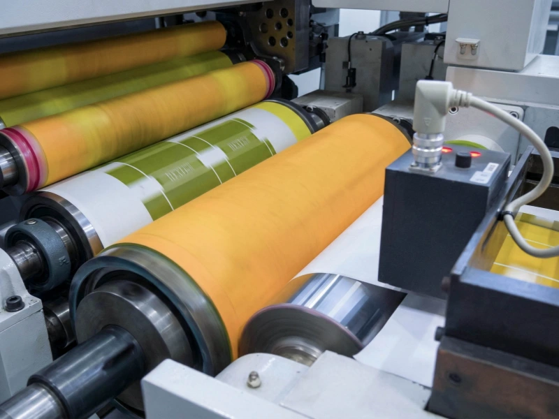
packaging film gravure printing roller line

What the Defect Pattern Reveals

Before changing ink, pressure, speed, or ESA, keep a print sample and mark the affected image area. Compare the same area over several cylinder revolutions.

The position and repeat pattern often tell more than a general description such as “light print.”

Isolated Missing Dots

Isolated missing dots are individual cells that leave no visible ink. They may appear as clean white points in a halftone or as small breaks inside a solid.

When the same dots return at the same image coordinates, inspect the corresponding cells on the gravure cylinder. Typical checks include dried ink, contamination, damaged cells, and shallow cells that are emptying before reaching the substrate.

A simple comparison can narrow this quickly:

  1. Mark a small image area on a retained sample.
  2. Clean the suspected cylinder area using the approved production procedure.
  3. Keep the other press conditions unchanged.
  4. Print the same image and compare the marked area.

If most of the same dots disappear, stay with cell cleanliness and ink condition. If exactly the same cells remain blank, inspect the engraving condition more closely.

Random dots behave differently. When their position changes between impressions, fixed cell damage becomes less likely. Loose particles, substrate texture, changing ink condition, intermittent contact, and ESA response deserve more attention.

Locally Weak Solid Areas

A locally weak solid usually involves a group of neighboring cells. It may look pale, cloudy, or slightly open compared with the surrounding ink film.

A patch fixed to the cylinder image usually leads back toward the cylinder, doctor blade, or ink condition.

A patch that appears only on one material roll, one printing side, or one visibly rough area points more strongly toward the substrate.

If different cylinders, inks, or substrate lots have already been compared and the same print unit remains weak, start looking more closely at the contact in that unit. A repeatable response to an approved impression adjustment makes that evidence stronger.

Incomplete Halftone Transfer

Incomplete halftone transfer often appears grainy or peppered.

Highlight and middle-tone cells carry less ink than deeper cells, so they tend to show drying, premature emptying, weak surface contact, or insufficient ESA assistance earlier.

The tonal pattern matters. Missing highlight dots with acceptable dark tones point in a different direction from an entire solid printing weakly.

Record the condition in a way that another operator can reproduce:

Highlight dots missing in unit four after the press warms up. Dark tones remain acceptable.

That gives the next shift a useful starting point. “The print is light” does not.

For rubber-covered roller positions around print contact, material transport, and printed-surface handling, see Printing Industry Rollers.

Do the Cells Reach the Nip with Usable Ink?

The engraved cells need to arrive at the nip with enough fluid ink left to transfer.

A gravure cylinder can look clean from normal viewing distance while fine cells remain partly blocked. Clean the suspected area using the approved method, keep the other production conditions stable, and compare the same image position again.

A clear improvement keeps the investigation at the cell and ink stage. Additional impression pressure cannot reopen a blocked cell.

Doctor blade condition also changes how much ink remains in shallow cells.

Excessive blade pressure, an unsuitable blade angle, poor support, vibration, or a damaged blade edge can disturb or remove ink before the cells reach the substrate. Fine tones often show the effect first because the available ink volume is smaller.

Ink condition also needs to be checked while the press is actually running. Useful comparisons include:

  • the first impressions after a stop versus stable running;
  • the start of the run versus the warmed-up press;
  • before and after an approved viscosity or solvent correction;
  • before and after ink filtration or cylinder cleaning;
  • before and after a controlled doctor blade adjustment.

Missing dots that appear mainly after a stop can indicate drying in fine cells.

A defect that slowly increases during a longer run can follow viscosity drift, solvent loss, rising press temperature, or contamination building in the ink circuit.

If a doctor blade adjustment changes the highlight dots immediately, keep the investigation around doctoring and ink release. Hold the impression setting steady during the comparison so the two effects do not become mixed.

For other roller positions involving ink, coating liquid, adhesive, or treatment-media pickup and release, see Transfer Rollers.

Can the Substrate Receive the Full Cell Pattern?

The cells can be properly filled and still fail to transfer ink to every point on the substrate.

Paper, board, decorative stock, and textured materials first contact the engraved cylinder at their highest surface points. Lower areas may remain outside effective contact.

The printed result can be a few missing cells, a pale patch inside a solid, or an open-looking halftone.

Compressibility matters alongside roughness. Two paper grades may look similarly rough, yet one compresses enough in the nip to close small surface gaps while the other leaves more unprinted points.

Films and coated substrates need a different visual check. Their surfaces may look smooth but still have local treatment variation, coating inconsistency, dust, particles, or contamination.

Also note whether the problem begins after a roll or lot change.

A direct substrate comparison is often enough to separate this stage:

  1. Keep the cylinder, ink, speed, impression setting, and ESA unchanged.
  2. Run the same image on a known stable substrate or another approved lot.
  3. Compare the same tonal area and image position.
  4. Check whether the missing dots remain fixed to the image or move with the material.

When the defect follows the material lot, printing side, or visible texture, continue with the substrate.

Higher impression pressure may temporarily close some of the gaps, but it can also change gloss, compress the material, distort sensitive stock, or create new contact marks.

If additional pressure improves the print, that confirms physical contact is involved. It does not identify the impression roller as the source of the original substrate difference.

When the Impression Roller Deserves a Closer Look

The impression roller becomes a stronger lead after the cell, ink, and substrate checks have been separated and the defect still responds to the nip.

Useful signs include:

  • the same defect changes repeatably after an approved impression adjustment;
  • the problem begins after impression roller replacement, grinding, or re-covering;
  • different cylinders, inks, or substrate lots have been tried, but the same print unit remains weak;
  • the defect changes with line speed while ink condition remains stable;
  • the roller surface shows glazing, contamination, dents, local wear, swelling, or other damage;
  • the defect repeats at a distance related to the impression roller circumference.

An improvement after adding pressure is useful evidence, but it should not be treated as the final setting.

Extra pressure may close small contact gaps while increasing cover deformation, heat, wear, substrate compression, or marking.

Inspect the impression roller as part of the full contact position.

Check the complete rubber-covered face and both edges. Look for polished bands, contamination, dents, swelling, and uneven wear. Compare the outside diameter and hardness with the previous stable roller when records are available.

Also check the shaft, bearings, mounting, alignment, and any available runout records.

A roller may look normal while the press is stopped and behave differently at production speed. Bearing movement, runout, roller deflection, heat buildup, or changes in the cover surface can make contact less consistent as speed rises.

For wide presses, note where the weak transfer appears across the working width. A problem concentrated near one edge, through the center, or in a narrow local band can point to different contact conditions.

For more detail on controlled nip contact, pressure distribution, roller profile, and running accuracy, see Pressure Rollers.

NBR / Nitrile Rubber Rollers are used in selected ink and industrial media-contact positions. NBR by itself does not define a gravure impression roller. The ink, solvent, cleaning liquid, hardness, surface finish, cover construction, bonding, speed, and previous roller history still need to match the actual position.

Detailed cover selection, hardness direction, and roller construction should be confirmed for the individual roller project.

Does the Result Change When ESA Is Switched?

Mechanical impression and ESA both affect the final ink-transfer point, but their effects can be separated with a controlled comparison.

Mechanical impression brings the substrate into physical contact with the ink-filled cells. ESA assists ink movement from the cells toward the substrate through the press's electrostatic printing system.

This assistance can be especially useful where fine cells or uneven substrate surfaces make complete transfer difficult.

An ESA on/off comparison should follow the press and ESA supplier's approved operating procedure. Keep the ink, cylinder cleanliness, substrate, speed, and mechanical impression setting unchanged during the comparison.

Mechanical contact remains the stronger lead when the defect changes with impression setting while the ESA condition stays the same. A problem that begins after impression roller work strengthens that direction.

The ESA branch becomes more relevant when missing dots consistently increase with ESA off and decrease with ESA on. The difference is often easier to see in fine halftones or on rougher substrates.

Little or no change between ESA on and off sends the check back toward the cells, ink, substrate, and mechanical contact.

ESA cannot reopen a blocked cell or replace ink that dried or left the cell before reaching the nip.

An ESA impression roller also needs to match the press and its electrostatic-assist system. General charge-control information is available on Anti-Static / Conductive Rubber Rollers, but a standard anti-static roller specification should not be used as an ESA impression roller specification.

Electrical inspection, resistance requirements, grounding, and high-voltage work should follow the equipment supplier's documentation and remain with qualified personnel.
Use One Controlled Test at a Time

A long troubleshooting report is rarely necessary. One marked image area and one controlled change usually provide clearer evidence.

Transfer Stage Evidence on the Press Next Check
Engraved cell The same dots stay fixed to the cylinder image; approved cleaning changes them Clean and inspect the corresponding cells; check contamination and engraving condition
Ink release The defect changes after a stop, during warm-up, with viscosity or drying changes, or after a blade adjustment Restore the approved ink condition; inspect blade edge, support, angle, pressure, and stability
Substrate surface The defect follows the material lot, printing side, particles, roughness, coating, or visible texture Compare a known stable substrate without changing the other press conditions
Impression contact The defect responds to pressure, speed, roller condition, or recent roller work Inspect the impression roller surface, mounting, diameter, hardness record, and runout
ESA assistance ESA on/off changes the same defect while the other conditions remain stable Follow the equipment supplier's ESA inspection route and confirm roller compatibility

For the affected print unit, record:

  • print unit and color;
  • isolated dots, weak solid, or incomplete halftone transfer;
  • marked image position;
  • substrate type, lot, printing side, and visible surface condition;
  • ink viscosity or control record and any drying change;
  • line speed;
  • impression setting;
  • impression roller hardness, if recorded;
  • ESA on or off;
  • one photo or retained sample before and after each change.

For repeated missing dots, count the dots inside the same small image window or mark the affected area on the retained sample.

The count does not need to become a formal quality limit. It only needs to show whether the controlled change affected the same defect.

Changing cleaning, viscosity, pressure, speed, and ESA together may improve the print, but it will not show where the transfer originally failed.

Related Pages

Learn More About Wolorin's Roller Manufacturing

  • Services — Custom rubber roller manufacturing, replacement, and suitable re-covering projects.
  • Quality Control — Inspection of roller dimensions, hardness, surface condition, runout, and project-specific requirements.
  • About Wolorin — Wolorin's background in custom industrial rubber rollers.

Send the Roller Information You Already Have

When the evidence points to an impression roller or another rubber-covered contact roller, Wolorin can support the roller part of the project through custom manufacturing, replacement, suitable re-covering, quotation, or production confirmation.

Press settings, ink formulation, substrate treatment, and ESA electrical servicing should remain with the press manufacturer, ink supplier, substrate supplier, or qualified ESA specialist.

For a roller project, send the information you already have:

  • roller drawing or basic dimensions;
  • outside diameter and rubber-covered face length;
  • shaft-end and bearing details, if available;
  • old roller photos showing the full face and both ends;
  • close photos of glazing, wear, dents, cracks, swelling, contamination, or other surface changes;
  • roller position and print unit;
  • ink, solvent, cleaner, or other contact media;
  • current cover material and hardness, if known;
  • the current roller-related problem and when it began;
  • whether the roller was recently replaced, ground, or re-covered.

If you already have drawings, dimensions, a sample, or a clear specification, send them directly. Wolorin can proceed with custom manufacturing, quotation, or production confirmation from those documents.

If the information is incomplete, start with old roller photos, basic dimensions, the roller position, contact medium, and the current roller-related problem.