
Map the Density from Left Edge to Right Edge
“Light at the edge” describes what the operator sees, but it is still too broad for troubleshooting. Fix the measurement positions before changing the press. Left, center, and right are a practical starting point. If a visible band sits between them, add readings inside the band and immediately beside it.
Use the same solid, tonal patch, or repeatable image area at every position. Take the readings close together in time. If the left side is measured on a solid and the right side on another tonal area several minutes later, normal changes in ink condition can distort the comparison.
A Simple Cross-Web Record
| Where to measure | What to record | Keep with the sample |
|---|---|---|
| Left side | Density or gray value and distance from the reference edge | Print unit and color |
| Center | Density or gray value | Substrate type, thickness, roll or lot |
| Right side | Density or gray value and position across the web | Line speed and impression setting |
| Visible band | Reading inside the band and readings beside it | Web width and sampling time |
The individual numbers matter less than the shape they form. For example, left / center / right readings of 1.42 / 1.51 / 1.43 form a roughly symmetric center-heavy profile. Readings of 1.40 / 1.48 / 1.50 show a different problem because density is rising toward one side. These figures are only examples of profile shape; the approved print target for the actual job remains the quality reference.
Keep using the same measurement positions during later trials. A fixed band is much easier to trace when its position is always recorded from the same reference edge.
Read the Shape Before Changing the Impression Roll
Both Edges Are Light and the Center Is Darker
When both edges are lighter by a similar amount, compare other colors on the same substrate first.
If several print units show a similar edge-to-center shape, inspect conditions shared by those units. Cross-web differences in substrate thickness, compressibility, coating, treatment, or surface condition can change how evenly the material enters impression contact.
If only one color shows the problem, stay with that unit. Ink condition and circulation, the gravure cylinder, doctor blade contact, contamination, and the unit’s impression condition are more useful checks at this stage.
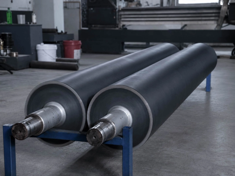
When those comparisons leave the same symmetric profile in place and impression adjustment repeatedly makes the center-to-edge difference stronger or weaker, the loaded profile of the impression roll becomes more relevant.
One Side Stays Lighter
For a one-sided problem, track the weak side through each controlled change.
If changing the substrate roll moves or removes the weak side, inspect the material profile. Thickness, coating, treatment, and compressibility can vary across the width even when two rolls carry the same nominal specification.
If several substrate rolls give the same result on one print unit, move back to that unit. Check the cylinder, doctoring, ink delivery, and lateral impression condition.
If different substrates and different cylinders still leave the operator side or drive side consistently weak, the machine-side geometry deserves attention. Parallelism, loading at the two ends, bearings, shaft support, and the impression roll then belong in the same mechanical check.
A Band Stays at the Same Width Position
A fixed band gives you an exact axial position to follow. Record its distance from one reference edge.
Suppose a darker band stays 300 mm from the operator-side edge after a substrate change and remains at the same position after changing the gravure cylinder. The fixed position is now more useful than the description “pressure band.” It tells you where to inspect the contact system.
Useful checks at that axial position include local outside diameter, cover condition, hardness consistency, grinding profile, loading, and nearby mechanical support.
If the band moves with another substrate roll, stay with the material. If it disappears with another cylinder or print job, continue on the print-unit side.
Scattered missing dots belong to another gravure-transfer problem. Gravure Missing Dots: Ink Transfer Checks covers that defect separately.
If a mark repeats at a regular pitch along the machine direction rather than staying in one cross-web position, compare the repeat distance with rotating components. Why Repeat Marks Appear on Web Materials covers that pattern.