Current Collector Foil Wrinkles Before Electrode Coating

Bare copper or aluminum foil may develop a long machine-direction ridge, a rippled edge, or a loose local lane before it reaches the electrode coating head. The foil then enters the coating area unevenly. One side may lift, a loose lane may move across the width, or the web may no longer remain stable at the coating entry.

These patterns need different checks. A longitudinal wrinkle often follows a persistent tight–slack lane. An edge wave points toward excess effective length or lower loading near the edge. A local buckle or baggy lane is more closely tied to a limited section of the incoming roll, winding history, or a splice.

Record the wrinkle shape, its measured position across the foil width, and the first span where it becomes visible. Then compare a second incoming roll, the foil around a splice, one small entry-path correction, and one controlled unwind change. These comparisons show whether the pattern follows the material, stays on one side of the machine, or begins after a specific contact point.

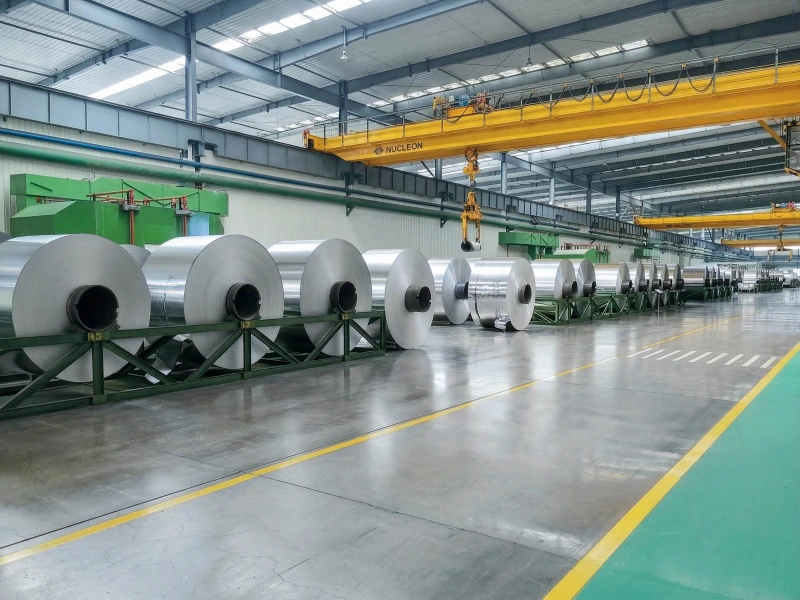
aluminum coil storage and processing workshop

What the Wrinkle Shape Tells You

Pattern Cross-web location Likely condition Best comparison test
Longitudinal wrinkle One fixed lane, several parallel lanes, or one side of the foil Persistent cross-web length or tension difference; incoming flatness variation; skewed entry span Run an unspliced section from a second roll without changing the entry path
Edge wave One edge or both edges Excess effective length near the edge; edge-shape variation; uneven edge loading; machine-side path bias Change the incoming roll and see whether the wave follows the material edge or remains on the same machine side
Local buckle or baggy lane Broad loose lane, isolated bulge, diagonal pocket, or slightly wandering slack area Local flatness variation; winding compression; splice distortion; limited-length slack Compare the foil immediately before, through, and after the splice

Measure the pattern from a known material edge. Terms such as “left side” become unreliable when the operator position, camera direction, or winding direction changes.

A clear record can follow this format:

Pattern type: longitudinal ridge Cross-web position: ___ mm from the operator-side foil edge First visible point: free span after entry roller ___ Duration: continuous / limited roll section / splice-related Incoming roll ID: ___

Use the same reference points for every roll. This makes photographs, videos, and production notes comparable.

Read the Three Patterns Differently

Longitudinal Wrinkles Follow a Tight–Slack Lane

A longitudinal wrinkle runs in the machine direction and remains within a limited part of the foil width. It may appear as one distinct ridge or several shallow parallel lines.

When the ridge is visible soon after unwind and stays at the same distance from the material edge, the incoming roll carries the strongest early evidence. The foil may already contain a cross-web length difference created during upstream rolling, slitting, winding, storage, or handling.

Average unwind tension can remain steady while one lane carries more load than the lane beside it. The looser lane contains surplus length. It may look flat while supported against a roller and rise again in the next free span.

Roll diameter adds another useful observation. A wrinkle that appears only during one part of the roll often follows a local winding condition. A ridge that remains from the outer layers toward the core suggests that the cross-web difference continues through a larger part of the roll.

Change the incoming roll before making several machine adjustments. When the ridge disappears or moves to another position relative to the material edge, incoming flatness and winding history move higher on the list. When different rolls develop the same ridge on the same machine side, the entry path deserves more attention.

Edge Waves Follow Either the Material Edge or the Machine Side

An edge wave appears as repeated rippling along one or both foil edges. It may be hard to see while the foil is supported against a roller and become clear in a longer free span near the coating entry.

The affected edge has more free length, or carries less effective load, than the center. Possible sources include incoming edge shape, uneven roll build, edge damage, storage compression, and a path that loads the center and edge zones differently.

The most useful observation is what the wave follows.

When one edge of a specific incoming roll remains wavy and the next roll enters flat under the same path, examine the incoming roll. Look for an uneven roll face, soft edge zones, telescoping, edge damage, or local compression.

When different rolls repeatedly develop a wave on the same machine side, examine guide alignment, steering response, and the angle at which the foil enters the next span.

Both edges may wave while the center remains relatively tight. This often shows that the center is carrying more effective load than the two edge zones. A one-sided wave gives stronger evidence of an asymmetric roll condition or machine-side path difference.

Higher total tension may temporarily pull the edge flatter. Watch whether the wave returns when the original running condition is restored. Also note whether its position changes. These observations carry more value than the temporary visual improvement.

Local Buckles and Baggy Lanes Often Have a Clear Beginning and End

A local buckle may appear as a soft bulge, a diagonal pocket, or a broad loose lane. A baggy lane may drift slightly across the width, disappear for a short distance, and return.

The affected roll length helps narrow the direction. A buckle limited to one part of an unspliced roll points toward local flatness or winding history. A buckle that begins as a splice enters the path points toward the splice.

A skewed splice brings one side of the foil under load before the other. Uneven tape placement, trapped foil, excessive overlap, or a local tension change during joining can leave one lane longer than the neighboring area. The loose lane may continue after the splice has passed while the load redistributes across the foil.

Observe the complete passage:

  • the foil shape before the splice arrives;
  • the shape while the splice crosses the entry rollers;
  • the first unspliced section after the splice;
  • whether the buckle fades quickly or continues through a longer section.

A single photograph taken at the splice cannot show this sequence.

A baggy lane that remains through a long unspliced section moves attention back to the incoming roll. A buckle that begins after the same machine position on different rolls moves attention toward the path or contact at that position.

Separate the Incoming Roll, Splice, and Entry Path

Each comparison should change one condition while the other running conditions remain as stable as production allows.

Change the Incoming Roll

Run an unspliced section from a second copper or aluminum foil roll. Keep the entry path, guide positions, unwind mode, and line speed close to the first run.

Compare three reference points:

  1. The measured distance from the material edge.
  2. The position relative to the machine frame.
  3. The first roller or free span where the wrinkle becomes visible.

A wrinkle that stays at the same distance from the material edge follows the material more closely. A wrinkle that returns to the same machine-side position on different rolls points more strongly toward the entry path.

Record the roll ID, winding direction, visible roll-face condition, known flatness information, storage condition, and any signs of local compression. Compare different foil materials, widths, or thicknesses through their actual running response. The same machine setting may not produce the same cross-web condition on every roll.

Compare the Complete Splice Passage

Record the same viewing area before, during, and after each splice. A fixed camera angle or marked observation point makes the change easier to read.

When production allows, remove a questionable splice and remake it from a clean, flat section. Keep the path and general tension condition unchanged.

If the buckle disappears after the splice is remade, the result gives strong evidence of splice-related distortion. If the wrinkle remains unchanged before, during, and after the splice, continue with the incoming-roll and path comparisons.

Make One Small Entry-Path Correction

A small change in guide position, steering action, or foil entry angle can show whether the path is redistributing load across the width.

Guide Rollers deserve attention where the foil changes direction, enters a long free span, or receives repeated steering corrections. Compare the foil shape before and after one small correction. Avoid making a large path change that hides the original pattern or creates a second wrinkle.

Use Unwind Tension as a Controlled Comparison

A controlled unwind change can show whether the wrinkle responds to overall load. Continue tracking the cross-web position while the tension changes.

Tension Control Rollers become relevant when the wrinkle changes during acceleration, deceleration, roll-diameter change, or a transition between tension zones.

A wrinkle that becomes smaller but remains in the same material lane still carries evidence of a local length difference. A wrinkle that moves across the width suggests that the path or steering action is changing the tight–slack boundary.

For wider wrinkle mechanisms across film, paper, foil, and other roll-to-roll materials, see Web Wrinkles in Roll-to-Roll Lines.

Check a Roller Only When the Wrinkle Begins After Contact

A roller-related check becomes useful when the foil is visibly flatter before a contact point and changes immediately after it.

Observe both spans around the suspected roller. Two fixed camera positions often show the change more clearly than watching the roller itself.

The pattern indicates where to look:

  • The wrinkle moves after a small alignment correction: compare roller parallelism, guide position, and foil entry angle.
  • Foil tightness changes once during each roller revolution: inspect runout, bearing condition, shaft seating, and rotation stability.
  • One lane hesitates, clings, or releases later than the surrounding foil: inspect deposits, contamination, surface damage, and local drag.
  • The foil lifts after a cleaning contact: confirm that the roller turns freely and that the surface is not pulling one local lane.
  • The wrinkle begins near one roller edge: inspect that edge for deposits, damage, uneven wear, or a different surface condition.

A roller may look clean under normal lighting and still create local drag. Side lighting can reveal fine particles, tape adhesive carried from a splice, polished contamination, shallow dents, and narrow wear bands.

For sensitive bare-foil positions, Lithium Battery Line Rollers covers roller requirements around guiding, tension contact, clean contact, and low-damage handling.

Where static attraction makes foil cling unevenly or collect particles, Anti-Static / Conductive Rubber Rollers may be relevant together with the actual grounding arrangement.

Where foil passes through a cleaning contact before coating, Cleaning and Sticky Rollers should remove particles without adding excessive tack or pulling one lane out of shape.

For broader handling requirements on copper foil, aluminum foil, and thin metal strip, see Foil and Metal Strip Processing Rollers.

Keep runout, parallelism, surface finish, and roller cleanliness behind the contact-point evidence. A wrinkle already visible near the unwind remains an incoming-roll or upstream-path issue.