Battery Electrode Slitting Problems: Burrs, Edge Chipping, and Particle Generation

A coated and calendered battery electrode may look acceptable on the parent roll, then leave the slitter with a raised metal edge, broken coating, or loose particles. These defects are often found in the same area, but they begin in different parts of the electrode.

Metal burrs form at the aluminum or copper current collector. Coating chipping starts at the newly formed active-layer edge. Cutting particles may come from the collector, the coating, or both, then move with the waste edge, extraction airflow, static charge, or downstream contact.

Inspect the electrode as close to the knife exit as production allows. A defect already visible there points first to the blade, cutting relationship, electrode structure, local support, tension, vibration, or extraction. When the edge leaves the knife clean and changes after a later contact, the next guide, traction, cleaning, or rewind position deserves attention.

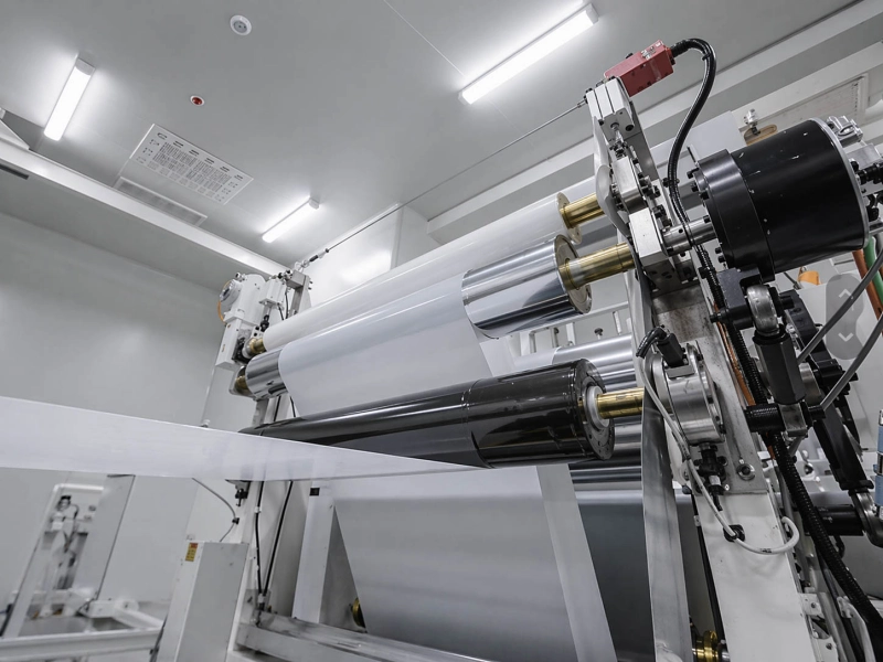
battery separator film roller line

Where the Three Defects Are Generated

Defect Generated at Carried or amplified by Evidence that helps most
Metal burr Cut edge of the aluminum or copper current collector Unstable blade contact, collector movement, local vibration, weak support, later edge rubbing Both sides of the slit, burr direction, knife position, measured height if available
Coating edge chipping Active-layer edge beside the new slit Coating fracture, local adhesion loss, blade impact, web movement, downstream edge contact Chipping width, exposed collector, fragment shape, affected side of the slit
Cutting particles Knife zone, from collector fragments, coating fragments, or both Extraction airflow, waste-edge movement, static, machine surfaces, guides, traction contact, rewinding First visible position, deposits around the knife, particle appearance and composition

The position with the heaviest deposit may be a collection point. A downstream guide can gather particles generated at the knife. Rewinding can press loose debris into the coating and make the contamination easier to see.

A simple three-position comparison usually gives a clear direction:

  1. before the knife;
  2. immediately after the knife;
  3. after the first important downstream contact.

Particles already present before the knife belong more strongly to incoming contamination. Particles appearing at the knife exit belong more strongly to cutting. A clean knife-exit sample that changes after one contact points toward downstream pickup, transfer, shedding, or redeposition.

For the wider set of electrode coating, calendering, slitting, clean transport, and winding positions, see Lithium Battery Line Rollers.

Why Metal Burrs Form at the Current Collector Edge

A metal burr is a deformed part of the current collector. It may appear as a raised lip, a folded foil edge, a sharp projection, or a fine needle extending from the aluminum or copper.

The blade loads and deforms the foil before the metal fully separates. A stable cut keeps that deformation limited. Blade wear, a small edge chip, coating buildup, holder movement, or unstable contact can stretch or fold the foil as it leaves the cut.

A cathode slitting burr and an anode slitting burr are both collector-edge defects, even though the collector material and electrode structure differ. The coating surrounding the foil still affects the result because the blade is cutting a layered electrode rather than bare metal.

Read the Burr Direction and Lane Pattern

The distribution of the burr often tells more than its general appearance.

If lane 4 has a heavy burr while lanes 3 and 5 remain stable, begin with the fourth knife position, its holder, local deposits, and nearby support. Changing the complete slitter setup at this stage can hide a local fault.

Photograph both sides of the same slit separately. One side may show a folded exit edge while the opposite side remains comparatively clean. That pattern can reflect asymmetric blade loading, an uneven blade relationship, or a support difference across the cut.

Blade service time also matters. A burr that grows gradually during the run points toward wear or buildup. A sudden change after maintenance points more directly to installation, holder position, blade contact, or contamination.

A controlled knife-position exchange can provide strong evidence. When the defect moves with the knife, the blade or holder becomes the main direction. When it remains in the same lane, local support, web entry, or machine-position factors deserve more attention.

Cutting Mode, Overlap, and Clearance Must Be Read Together

Shear, crush, razor, and other cutting systems load the electrode differently. Each system has its own relationship between blade position, overlap, clearance, support, and web entry.

A setting copied from another line may produce a different edge, even when both lines process copper anodes or aluminum cathodes. Collector thickness, coating thickness, calendered stiffness, blade geometry, holder accuracy, speed, and local support can all change the result.

Useful comparisons include:

  • the affected knife against a recently serviced knife;
  • the bad lane against the nearest good lane;
  • both sides of the same slit;
  • the edge before and after blade cleaning;
  • the same knife before and after holder work;
  • the beginning and later part of the blade service period.

Change one main condition at a time. Simultaneous changes to tension, speed, overlap, cleaning, and support make the result difficult to interpret.

The Collector Must Stay Stable During Separation

Thin foil can move during the short moment when the blade loads and separates it. Local lifting, flutter, vibration, a changing entry angle, uneven cross-web tension, or a support gap can alter the cut.

Observe the affected lane closely. A short video taken from the same angle during a good run and a bad run can reveal movement that is difficult to see in still images.

Higher tension may make the electrode look flatter, but it cannot restore a worn blade or remove a support gap. When several lanes change together with tension, inspect the common tension zone and support arrangement. When one lane remains abnormal under the same conditions, return to that knife position.

For guide, support, tension, and transport positions around the slitting section, see Slitting and Rewinding Line Rollers.

Why the Active Coating Breaks Along the Slit Edge

Coating edge chipping may appear as a narrow missing strip, an irregular broken edge, exposed collector, loose flakes, or a powdery line beside the slit.

The metal edge underneath may still be acceptable. In that case, the damage sits within the active layer or at the coating-to-collector interface.

The coating does not deform like metal foil. It is a compacted structure made from active-material particles, conductive material, binder, and internal pores. During slitting, it can crack within its own thickness, separate locally from the collector, or break together with a small piece of foil.

Cohesive Breakage and Interface Separation Look Different

Two common edge patterns are worth separating.

Cohesive breakage occurs inside the coating. The edge often looks granular, powdery, or irregular. Thin flakes may come away while part of the coating remains attached to the collector.

Interface separation occurs between the coating and the collector. It can leave a cleaner strip of exposed foil beside the slit. On an anode, this may be described as edge delamination. Similar separation can also appear on a cathode when the local interface loses support during cutting.

A fragment containing coating and a small piece of metal shows combined damage. The collector and active layer were disturbed together.

Clear close-up images usually provide enough information for this first distinction. General descriptions such as “the coating is falling off” leave out the shape, side, and width of the damage.

The Chipping Pattern Shows Whether the Problem Is Local or Wider

A continuous narrow strip beside one knife position points more strongly toward a local blade, support, or entry condition.

Random chips across several lanes suggest a wider change in the electrode or knife zone. If all lanes change after a new coating batch or calendering condition, compare the incoming electrode structure. If one lane changes after blade work, stay around that knife.

The affected side also matters:

  • single-side chipping can follow asymmetric blade loading or support;
  • similar damage on both sides can reflect a wider coating or knife-zone condition;
  • fine powder points more strongly toward surface fracture or rubbing;
  • thin flakes point toward breakup inside the active layer;
  • a clean exposed collector strip points toward local interface separation;
  • mixed metal-and-coating fragments show combined edge damage.

Calendering Changes the Structure Reaching the Knife

Calendering reduces electrode thickness, compacts the coating, and changes the stiffness of the complete electrode. A web can run steadily through the machine and still fracture sharply when a new edge is formed.

A denser coating may produce a clearer fracture line. A locally weak interface may remain hidden on the parent roll until the cut removes side support. This can leave a stable metal edge with a narrow coating-loss band beside it.

When the same knife setup produces different results between electrode batches, record the coating and calendering condition. The purpose is to confirm whether the structure entering the knife has changed, rather than to apply one standard setting to every electrode.

Check the Electrode Before It Reaches the Knife

Cracks, local delamination, handling damage, or weak coating edges may already exist before slitting.

Compare samples from the same lane before and immediately after the knife. Damage already present upstream belongs with coating, drying, calendering, or earlier handling. Damage first appearing at one knife position belongs with that cut.

The final Guide Rollers before the knife are relevant when the electrode enters at an angle, moves sideways, or shows unequal edge tension. Tension Control Rollers become more relevant when several lanes change together during acceleration, deceleration, or tension-zone movement.

Separator film has a different structure and failure pattern. Separator wrinkles, fuzzy edges, static, and cutting dust are covered in Battery Separator Film Slitting and Rewinding Problems.

How Cutting Particles Are Generated and Moved Downstream

Electrode cutting particles may be metallic, non-metallic, or mixed.

Fine bright fragments usually point toward the current collector. Dark or light powder often comes from the active coating, although colour alone cannot confirm the source. Larger flakes may contain coating attached to a small piece of foil.

Particle composition is useful when available. Even a basic distinction between metal, coating material, and unrelated contamination can shorten the investigation. Production evidence can still narrow the source before laboratory analysis.

Signs That the Knife Is Generating the Particles

Cutting-generated particles often follow a recognisable pattern:

  • fresh deposits appear below or beside one knife position;
  • particle quantity rises through the blade service period;
  • deposits remain close to a damaged slit edge;
  • particles return first around the knife after cleaning;
  • the composition matches the collector or coating;
  • the condition changes after blade cleaning, blade replacement, holder work, or support adjustment.

For example, powder that appears immediately after lane 6 is cut, remains low on neighbouring lanes, and increases as coating builds on that blade points toward a local cutting source.

Particles already spread across the full electrode before slitting require an upstream contamination review.

Extraction Must Capture Particles at the Release Point

An extraction fan may be running while local collection at the slit remains weak.

Inspect the hood position, suction path, internal deposits, blocked sections, distance from the cut, and interaction with the waste edge. A small web-path change can move the particle-release point away from the extraction opening.

Air direction matters. Light coating particles can cross into an adjacent lane when airflow travels over the slit rather than drawing debris away. One knife may then appear comparatively clean while the neighbouring lane receives more contamination.

After cleaning the knife and extraction area, observe where the first new deposit appears. The first return point is usually more useful than the total amount collected after a long run.

Escaped Particles Can Return to the Electrode

Particles that escape extraction may:

  • move with the waste edge;
  • settle on a support plate or machine frame;
  • attach to the electrode through static;
  • collect on a guide or traction roller;
  • transfer from one lane to another;
  • return to the electrode during later contact;
  • become pressed into the coating during rewinding.

A dusty roller face confirms that the roller lies in the particle path. Compare the electrode before and after that contact to determine whether the roller is collecting debris, transferring it, or causing secondary damage.

Where the process allows, Cleaning and Sticky Rollers can remove loose particles before a sensitive downstream contact. The surface must remain clean and stable. Shedding, residue transfer, excessive tack, or high drag can introduce another problem.

Anti-Static / Conductive Rubber Rollers are relevant when charge buildup and the grounding path clearly influence particle movement. Static control cannot remove metal or coating fragments that continue to be generated at the knife.

If the electrode leaves the knife clean and develops scratches, particle impressions, or micro-compression after a roller contact, see Battery Electrode Web Surface Defects After Roller Contact.

When the Rollers Around the Slitter Are Worth Checking

The blade and electrode remain the main subjects when burrs, coating chipping, or fresh particles are already visible at the knife exit.

Rollers are worth checking when the evidence changes around a specific contact position.

Roller position What it can affect Useful field signal
Guide or support before the knife Entry angle, local lifting, flutter, lateral movement, cross-web tension distribution The electrode begins moving after one guide or one lane enters the knife differently
Guide or traction after the knife Lane path, edge rubbing, particle transfer, secondary chipping A clean slit edge changes after one contact
Cleaning or anti-static contact Removal, attraction, or release of loose particles Particles collect around the same surface or return after cleaning
Rewind contact Compression of loose debris and visibility of weak edges Particles or edge damage look worse only after roll build

A specific roller deserves closer inspection when:

  • the electrode moves visibly before the knife;
  • several lanes change together near one tension-contact position;
  • a clean edge becomes chipped after one downstream contact;
  • particles repeatedly collect on and return from the same roller surface;
  • one lane shows higher drag or a different running path;
  • the problem begins after roller replacement, grinding, bearing work, or alignment adjustment.

Inspect that roller rather than the complete line. Look at free rotation, bearing drag, alignment, runout, surface cleanliness, web entry and exit angle, and the lane position of deposits or wear.

A support roller can improve local stability. It cannot restore a worn blade. A cleaning roller can remove loose particles. It cannot replace effective knife-zone extraction. An anti-static roller can influence particle attraction when the electrical path is suitable. It cannot stop cutting fragments from being generated.

Wolorin’s role begins when the evidence points to the roller position itself: a guide, support, traction, cleaning, anti-static, or rewind-contact roller that needs replacement, a different cover or surface direction, or custom manufacturing for the actual contact condition.

Evidence That Makes the Cause Easier to Confirm

A useful sample pack should show what the defect looks like, where it first appears, and which lane or contact position is involved.

Evidence Details worth including
Slit-edge photos Both sides of the slit, lane number, machine direction, knife position, collector and coating visible where possible
Burr information Direction, affected length, measured height if available
Chipping information Width, location, exposed collector, fragment shape, affected side of the slit
Particle information First visible position, deposit position, appearance, and composition if known
Electrode details Cathode or anode, collector material and thickness, coating condition, calendering condition
Blade details Blade type, cutting mode, knife position, service time, cleaning and recent maintenance
Knife-zone condition Support layout, tension behaviour, visible vibration, flutter, lateral movement, entry angle
Extraction condition Hood position, suction status, deposits, blocked sections, waste-edge interaction
Post-slit path Guide, traction, cleaning, anti-static, and rewind contacts; first redeposition point
Roller information Drawing or basic dimensions, exact position, surface photos, material and hardness if known, recent repair or replacement

Keep lighting, magnification, and viewing direction consistent when comparing edge photos. Mark the machine direction and the exact side of the slit.

Position-specific labels are far more useful than general descriptions. “Operator-side edge of lane 4, immediately after the knife” can be compared with another sample. “Poor slitting quality” cannot.

The same applies to particles. “Dark powder first appears after lane 4 knife and before guide 1” gives a usable sequence. “Dust on the finished roll” does not show when the contamination began.

Measured burr height, chipping width, particle quantity, tension, overlap, and clearance can be recorded as project evidence. Their meaning must remain tied to the electrode structure, knife system, machine design, and the customer’s own quality requirements.

Related Pages

Roller Manufacturing and Quality Information

  • Services — Custom roller manufacturing, replacement, and production confirmation.
  • Quality Control — Inspection of roller dimensions, hardness, surface condition, runout, and project-specific requirements.
  • About Wolorin — Wolorin’s industrial roller manufacturing and supply direction.

Send Drawings or Existing Roller Details

Wolorin can support the roller-related part of a battery electrode slitting project when a guide, support, traction, cleaning, anti-static, or rewind-contact roller needs replacement or custom manufacturing.

If you already have drawings, dimensions, samples, or a clear roller specification, send them directly. We can proceed with quotation, custom manufacturing, or production confirmation based on those documents.

For an existing roller, the most useful starting information is:

  • roller drawing or basic dimensions;
  • outside diameter, face length, shaft, and bearing dimensions;
  • exact roller position on the line;
  • old roller photos, including both ends and the full working face;
  • which side of the electrode contacts the roller;
  • contact medium and cleaning medium;
  • current cover material, hardness, and surface finish if known;
  • visible deposits, cuts, dents, uneven wear, swelling, or surface damage;
  • the current roller-related problem, such as particle transfer, edge rubbing, unstable support, poor rotation, or repeated contamination.

If the information is incomplete, begin with old roller photos, main dimensions, roller position, contact medium, and the problem seen near that roller. These details are enough to start a normal replacement or custom-manufacturing discussion.