Steel Strip Bridle Roll Problems: Slipping, Tension Loss, and Speed Mismatch

A steel strip may slide visibly on one bridle roll, lose the required entry-to-exit tension difference, or become unstable during acceleration. These symptoms often appear together, but they do not point to the same fault.

Compare the threading route, entry and exit tension, actual roll speeds, drive torque or motor current, and main line speed on the same trend. If one driven roll cannot follow its speed command, the drive or transmission side should be cleared first. If the rolls stay at the expected speed while the tension difference falls under load, the wrapped contact deserves more attention. At that point, actual roll diameter, surface condition, wear, cover deformation, and the strip’s oil or liquid condition become useful evidence.

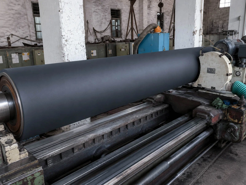
black rubber traction roller manufacturing

How a Bridle Stand Holds the Tension Difference

A bridle stand separates two tension zones by passing the strip around several rolls.

Entry tension
      ↓
Roll 1 → Roll 2 → Roll 3 → Roll 4
      Multiple wrapped contacts
      + controlled surface speed
      + distributed drive torque
      ↓
Exit tension

The strip enters under one tension and leaves under another. Each wrapped contact transfers part of the drive load to the strip. The work is spread across several rolls instead of being carried by one contact point.

The stand depends on three things happening together:

  • the strip follows the intended wrap path;
  • the roll surfaces move at the required speeds;
  • the contacts transfer enough traction for the current load.

A missed roll or a shorter threading route reduces the usable wrap. The stand may still run at steady speed or light load, then begin losing tension during acceleration or when a heavier strip enters.

Roll speed also needs to be read correctly. Shaft rpm is only part of the picture. Surface speed depends on both rpm and actual finished diameter. A roll that has been ground or re-covered to a smaller diameter can run at a different surface speed even when its shaft rpm matches the other rolls.

Once the path and surface speeds are correct, the strip still needs enough traction to follow the rolls as torque rises. Oil, water, cleaner residue, glazing, wear, diameter variation, or cover deformation can reduce that traction margin.

For roller positions that transfer pulling force through surface contact, see Traction Rollers. Powered roller arrangements are covered under Drive Rollers, while Tension Control Rollers provides the wider functional background for tension-related positions.

Three Ways the Problem Shows Up on the Line

The line signals usually fall into three patterns.

What you see What to clear first When the roll contact becomes relevant
The strip visibly slides while torque rises Threading, wrap path, and actual surface speed The roll reaches speed, but the strip still slides at the same contact
The tension difference falls without visible slip Tension-zone response, load changes, and measurement Roll speeds stay stable, but the maintained tension difference falls under load
Roll speed or tension starts to oscillate Shaft-speed feedback, transmission, and actual diameter Shaft speeds stay stable, but tension and torque repeatedly rise and fall

When the Strip Clearly Slides on One Roll

This is the most obvious form of bridle roll slippage. The roll surface is moving faster than the steel strip.

Operators may see the strip hesitate at one roll, hear a change in contact sound, or find a polished band after shutdown. Drive torque or motor current often rises because the stand is trying to recover the required tension.

A common sequence is:

  1. The line runs normally at steady speed.
  2. Acceleration or heavier load increases the traction demand.
  3. Drive torque rises.
  4. The strip begins sliding at one contact.
  5. Entry and exit tension move away from their normal relationship.

Confirm the wrap route first. A missed roll or shallow wrap can move too much load onto the next contact.

Then compare actual roll surface speed with line speed. If the shaft itself is slow, unstable, or unable to follow its command, the drive and transmission side remains the stronger lead.

The roll contact moves to the front of the investigation when the wrap route is correct, the roll reaches the expected surface speed, torque continues to rise, and the strip still slides at the same position. Oil, water, cleaner residue, or a polished working band at that location adds useful evidence.

A generally shiny roll proves little by itself. A polished band that matches the actual slip position is far more meaningful.

When the Tension Difference Falls Without Visible Slip

A bridle stand can lose tension without producing one clear sliding point.

The entry tension may remain close to target while the exit tension falls. In other cases, the two readings move closer together as load rises. The strip may still look smooth to the operator.

Small relative movements can be spread across several wrapped contacts. Each movement is too small to create an obvious jump or slip mark, but together they reduce the tension difference the stand can hold.

Put entry tension, exit tension, actual roll speeds, drive torque, and line speed on the same time axis. Look for the first signal that begins to move.

If the tension change follows a dancer movement, downstream load change, or control-state change, the tension zones should be cleared first.

The wrapped contact becomes more relevant when all driven-roll speeds remain stable, torque rises normally, and the entry-to-exit tension difference weakens mainly at higher load. Dry strip running normally while oily or wet strip loses tension is another useful clue. Repeated short-term improvement after cleaning also points back toward the contact condition.

Until actual relative movement is confirmed, describe this condition as tension loss rather than visible slip.

When Speed or Tension Starts to Hunt

Speed mismatch appears in two different ways.

In the first case, one roll shaft cannot follow its speed command. It may lag during acceleration, overshoot, or move repeatedly above and below the target. That remains a drive, feedback, transmission, or control-side issue.

In the second case, the shaft-speed signals stay stable while strip tension and drive torque continue to rise and fall. The strip may be moving through a repeating grip-and-release cycle:

  1. The roll carries the strip.
  2. Torque and tension rise.
  3. The required traction reaches the available contact limit.
  4. The strip moves slightly against the roll surface.
  5. Torque and tension fall.
  6. Contact recovers and the cycle begins again.

The movement may be small. Operators may see the tension display hunting without seeing the strip make a large jump.

Actual finished diameter also matters. Two rolls turning at the same shaft rpm have different surface speeds when their diameters differ. For example, a 500 mm roll and a 498 mm roll differ in surface speed by about 0.4% at the same rpm. A small difference can remain present throughout continuous running.

After grinding, replacement, or re-covering, compare the finished diameters across the full bridle stand. In a mechanically linked arrangement, the mismatch remains on every revolution. Independently driven rolls may compensate only when the actual diameter is known and entered correctly.

For broader metal-strip roller positions, see Foil and Metal Strip Processing Rollers and Steel & Metallurgy Rubber Rollers.

Why Dry, Oily, and Wet Strip Behave Differently

The strip surface changes the traction available at every wrapped contact. It also changes the way the fault appears.

Strip condition What it helps reveal
Dry and stable Wrap errors, diameter differences, speed problems, and basic contact capacity
Oily Reduced traction margin during acceleration or higher load
Wet or liquid-covered Local slip, liquid carryover, or repeating grip-and-release

Dry Strip

Dry strip provides the clearest baseline.

If the stand loses tension on dry strip at a stable, moderate load, continue with the wrap route, actual surface speeds, tension signals, diameter, and mechanical condition. Oil-film behaviour cannot explain a fault that is already present under dry contact.

Oily Strip

“Oily” is too broad to be useful on its own. Record:

  • whether the oil film is light or heavy;
  • whether it is even or patchy;
  • whether it covers the full width or stays mainly on one side;
  • whether it changes through the coil;
  • which oil or lubricant is actually touching the roll.

Patchy oil can create an intermittent problem. The stand may run normally until a heavily oiled section reaches the bridle, lose tension for a short period, and then recover without any machine adjustment.

Identify the first roll that receives the oil. If the early contacts are heavily coated while later rolls remain relatively dry, the traction contribution can shift through the stand.

Wet Strip

Water, coolant, rinse liquid, or cleaner residue can form a moving film between the strip and roll.

Record where the liquid first enters the bridle and whether the strip becomes drier or wetter as it passes through. A contact that works at low speed may become unstable after acceleration when more liquid remains in the wrapped area.

A short improvement after cleaning usually points toward contamination or surface condition. A rubber cover that remains swollen, soft, tacky, hardened, or dimensionally changed after cleaning and drying points more directly toward cover compatibility or cover failure.

For oil-contact rubber-covered positions, NBR / Nitrile Rubber Rollers may be an early material direction. The actual oil, cleaning liquid, temperature, load, old roller condition, and required grip still control the final choice.

When to Inspect the Rubber-Covered Bridle Roll

Drive tuning, encoder calibration, and full tension-loop adjustment belong to the plant or equipment team.

The roller itself becomes a practical next step when the evidence stays close to one bridle roll: its dimensions, surface condition, cover behaviour, wear pattern, contact medium, or replacement history.

Actual Finished Diameter and Runout

Measure the actual finished diameter after grinding, replacement, or re-covering. Do not rely only on the original drawing.

When practical, measure near the drive side, centre, and operator side. This can reveal:

  • one roll finished smaller than the others;
  • taper across the face;
  • a worn working band;
  • an actual diameter that no longer matches the machine record.

Diameter affects surface speed. It also changes the wrap and how load is shared between contacts.

Runout creates a different signal. A tension or torque movement that repeats once per revolution makes eccentricity, local cover variation, or a damaged area more relevant. Irregular tension loss with no repeating cycle gives weaker support for runout.

Glazing, Contamination, and Cleaning Response

A shiny surface can come from oil residue, compacted contamination, repeated micro-slip, normal wear, or chemical change in the cover.

Take photos:

  • before cleaning;
  • immediately after cleaning;
  • after the next production run.

If cleaning restores stable traction and the surface stays clean, contamination was probably important. If the same polished band returns quickly, record where the oil or liquid enters and whether the strip slips at the same width position.

The way the line behaves after cleaning is more useful than a clean roller photo.

Wear Across the Roll Face

Inspect the full working face, both edges, and the boundaries of the normal strip width.

Useful signs include:

  • a step between used and unused areas;
  • heavier polish on one side;
  • local cuts, dents, or edge damage;
  • a worn band under the usual strip path;
  • different behaviour after changing strip width.

A roll may run normally with one strip width and become unstable with another. The new strip path may cross both worn and less-worn areas, creating uneven traction across the width.

Cover Deformation Under Load

A rubber-covered roll can measure correctly while stopped and still change shape under torque and strip tension.

Compare low-load and high-load behaviour. Also compare cold start with the condition after the line has been running for some time.

Record signs such as:

  • the working contact band becomes wider under load;
  • the centre or one edge compresses more heavily;
  • a local flat or soft area appears after shutdown;
  • traction is stable at low torque but falls at higher torque;
  • performance changes as the cover warms during production.

Cover deformation changes the effective rolling diameter at the contact. The unloaded diameter may be correct while the working surface is no longer behaving consistently.

Cover Condition and Previous Re-Covering

Inspect the cover after cleaning and drying.

Record:

  • swelling or diameter growth;
  • softening or hardening;
  • persistent tackiness;
  • cracks;
  • edge lifting;
  • bubbles or local debonding;
  • the same problem returning after grinding or re-covering.

These signs move the review beyond temporary oil-film behaviour. Compound direction, bonding, cover thickness, curing, grinding, and previous repair condition can all affect the result.

Two rollers both described as PU or NBR can still run differently because the material name does not describe the full cover system.

Polyurethane Rubber Rollers may be relevant where load support, wear resistance, and traction need to work together. NBR is often an early direction for oil-contact positions. The final choice should follow the actual contact medium, torque, temperature, surface requirement, and old roller failure.

If an existing roller worked well for years, its drawing, actual dimensions, hardness, surface finish, roller position, and old roller photos may be enough to begin a replacement. Repeated glazing, swelling, diameter change, or unstable performance after re-covering calls for a closer look at the complete cover construction.

For finished diameter, runout, hardness, and surface inspection, see Quality Control.
Save the 30–60 Seconds Around the Fault

Save a synchronized trend covering about 30–60 seconds before and after the event. Use the sampling resolution already available on the line.

Signal What it helps show
Entry tension Whether the incoming tension zone remained stable
Exit tension When the tension difference began to fall
Commanded and actual speed of each driven roll Whether one roll failed to follow its command
Torque or motor current for each drive Whether load increased normally or concentrated on one roll
Main line speed Whether the event began during acceleration, deceleration, or steady running

Add short notes beside the trend:

  • threading and wrap route;
  • dry, oily, or wet strip;
  • strip-width or load change;
  • first visible slip position;
  • cleaning, grinding, replacement, or re-covering before the event;
  • actual finished diameter of each bridle roll.

Mark the point where entry and exit tension begin moving closer together. Then look backward for the first signal that changed.

If one roll speed drops first, the drive side remains the stronger lead. If all roll speeds stay stable while torque rises and the tension difference falls, the wrapped contact carries more of the evidence.

A complete line-control report is not needed for a roller inquiry. A relevant trend screenshot is useful when it clearly connects the problem to one bridle roll position.

Related Pages

Manufacturing and Quality for Custom Rubber Rollers

  • Services — Custom manufacturing, replacement, selected re-covering, and surface finishing for industrial rubber rollers.
  • Quality Control — Inspection support for finished diameter, hardness, surface condition, and runout.
  • About Wolorin — Wolorin’s rubber roller manufacturing background and project approach.

Request a Quote

If you already have drawings, samples, an existing roller, or current specifications, you can send them directly for quotation. If the information is still incomplete, you can also start by providing the roller position, operating temperature, contact material, surface requirements, and the current problem.