Steel Pickling Line Rubber Roll Failures: Edge Swelling, Cracking, and Cover Separation

Cracking at the roller end, cracking beside a segment gap, and cracking across the full working face usually come from different failure paths.

End damage often starts where acid, rinse water, or cleaning liquid reaches the side of the cover. Damage around a segment gap can begin where liquid and scale remain between sections. A full-face change points to wider exposure across the roller surface.

Record the first damaged location before the roller is cleaned or stripped. Once acid enters a crack or reaches the steel core, the original failure can spread into swelling, rust, local lifting, and wider cover separation.

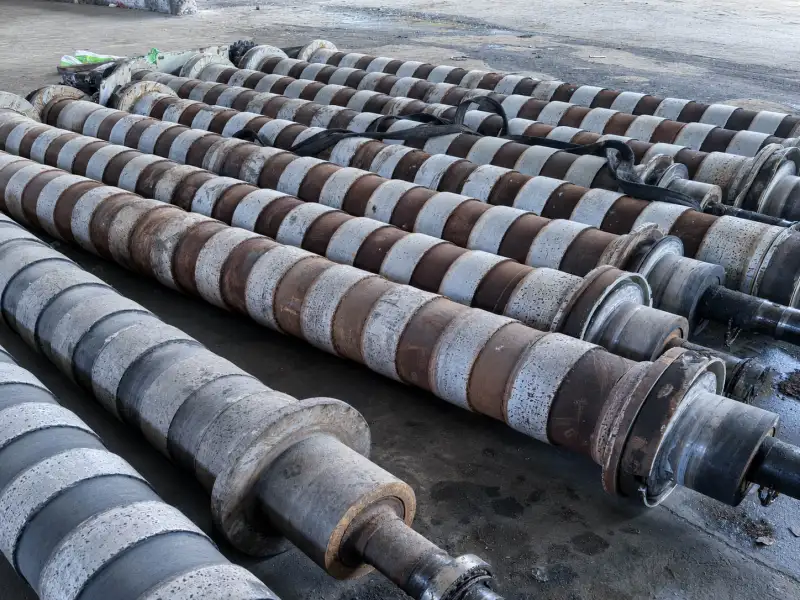
Stainless steel pickling line rollers

Where Did the Failure Start?

Inspect the roller before heavy cleaning. Keep acid stains, rust traces, loose rubber, crack direction, and the edge of the swollen area visible long enough to photograph them.

Mark the drive side, operator side, and rotation direction. Also record the roller position, such as acid contact, rinsing, squeezing, wet conveying, or another section of the pickling line.

Pickling-Line Roller Failure Map

LocationWhat it suggestsEvidence to confirmRoller implication
Full working faceBroad exposure to acid, spray, immersion, cleaner, or retained liquidSimilar swelling, hardening, cracking, or texture change across most of the faceReview the complete liquid-contact history and rubber direction
Working-face edgeLiquid pushed beyond the strip, edge pooling, squeeze-out, or weak edge protectionOne or both edges change before the centerReview strip width, wet-contact width, drainage, and cover ending
Roller end or end faceSide entry, splash, washdown, retained liquid, or exposed steelDamage begins at the end and moves inwardReview end protection, drainage, bonding coverage, and core condition
Segment gapTrapped liquid, exposed segment sides, scale, debris, or segment movementDamage follows one or more gaps around the circumferenceReview gap construction, side protection, and segment condition
Cover-to-core areaLiquid has reached the bonding layer or steel coreRust staining, hollow areas, bulging, or local separationInspect the bond and core before repeating the old construction

The Steel & Metallurgy Rubber Rollers page gives a broader view of rubber-covered roller positions used around steel strip treatment and handling.

What Each Location Tells You

Across the Full Working Face

Similar change across most of the working face points to broad exposure.

The roller may receive continuous spray, partial immersion, acid carried by the strip, or repeated wetting during production. Cleaning liquid and rinse water belong in the same record. They may touch the cover at a different temperature or remain on the surface longer than the process acid.

A roller left wet during shutdown also sees a different contact cycle from one that is rinsed and dried soon after production.

Check whether:

  • the changed area follows the normal wet zone;
  • the roller diameter has increased across the full face;
  • the center and edges feel equally soft or hard;
  • the surface remains changed after drying;
  • the failure appeared faster after a change in acid, cleaner, rinsing, or shutdown practice.

Broad swelling or surface change brings the rubber material into the review. General cracking, swelling, softening, and hardening are covered in more detail in Rubber Roller Failure Signs.

Along the Working-Face Edge

The working-face edge is the outer band of the rubber surface. It is separate from the roller end face.

The moving strip may wipe liquid from the center while the outer band stays wet. On squeeze positions, liquid can also move sideways through the contact area and collect near the end of the rubber cover.

Compare both edges and measure the width of the damaged band.

Damage on one side often follows strip tracking, spray direction, machine slope, or uneven drainage. Similar damage on both sides points toward the repeated cover-ending detail or liquid collecting outside the normal strip path.

Common signs include:

  • a raised or enlarged edge band;
  • rubber that feels softer or stickier than the center;
  • a circular crack close to the cover edge;
  • staining around the cover ending;
  • lifting that starts at the outer edge;
  • damage aligned with the normal strip edge.

For wet squeeze positions, the Squeeze and Dewatering Rollers page covers the roller requirements around liquid removal and wet contact.

At the Roller End

The roller end includes the area beside the working face where the rubber cover finishes.

Splash, overflow, washdown, and liquid running along the roller can reach this area. Rotation may carry some liquid away during production. After shutdown, residue can remain against the same cover boundary for hours.

End-entry failures often develop in this order:

  1. staining, softening, or swelling appears near the end;
  2. a crack or small opening forms around the cover ending;
  3. liquid moves beneath the rubber;
  4. rust or local lifting appears farther inward.

Repeated failure on the same machine side is useful evidence. Photograph the nearby spray direction, drainage route, exposed steel, and any damage caused during cleaning or maintenance.

The next roller should address the end detail as well as the rubber material. A stronger compound cannot close an open path at the cover edge.

Around Segment Gaps

Every segment gap creates two rubber side faces and a narrow space where liquid, scale, or cleaning residue can remain.

The gap may open slightly while the roller is loaded. When the load is released, it can close around retained liquid or debris. Repeated movement damages the same edge and gives liquid more access to the segment side.

Inspect every gap, not just the worst one.

A single failed gap usually points toward local damage, poor assembly, trapped scale, or movement of one segment. Similar damage at most gaps points toward the repeated segment detail.

Record:

  • which gaps are affected;
  • whether the damage continues around the full circumference;
  • gap width at several positions;
  • the condition of the segment sides;
  • scale or hard debris inside the gap;
  • loose or moving segments;
  • repair or re-covering history.

A change from segmented to continuous covering can affect the roller’s original function and maintenance method. Any construction change should start from the roller position and the reason the segmented design was used.

Under the Rubber Cover

Local lifting or cover separation shows that the failure has reached the rubber-to-steel area.

Liquid can enter through an end opening, segment gap, deep crack, cut, or damaged cover edge. Once it reaches the steel, corrosion can spread under rubber that still looks intact from the outside.

Typical signs include:

  • rust staining at the cover edge;
  • a local bulge;
  • a hollow response when the surface is tapped;
  • lifting beside a crack or segment gap;
  • separation growing inward from one end.

After stripping the old cover, inspect the steel directly below the first damaged location. Photograph corrosion, pitting, previous welds, repaired areas, remaining adhesive, and any loss of the original core shape.

Deep corrosion can make the old core unsuitable for another covering cycle. The decision should be made after the damaged area is exposed and measured.
Does the Pattern Point to Chemical Exposure or a Structural Opening?

Chemical exposure usually affects an area. The rubber may swell, soften, become sticky, lose its original surface, harden after drying, or develop fine cracks across the wet zone.

Structural damage is often more concentrated. It may begin at one sharp edge, one segment, a cut, an exposed cover ending, or a weak area around the bond.

What you seeMain direction to investigate
Similar swelling across the wet areaAcid, cleaner, temperature, contact time, rinsing, and shutdown condition
One edge repeatedly failsStrip position, liquid flow, drainage, and cover ending
One roller end repeatedly failsSide exposure, retained liquid, exposed steel, and end protection
Most segment gaps show the same damageRepeated gap design, segment-side protection, and trapped liquid
Only one gap or one segment failsLocal damage, debris, assembly, or segment movement
Separation grows from rusted steelLiquid entry, core corrosion, and bonding condition
Failure appears soon after re-coveringOld core condition, end preparation, bonding, and repeated construction

The plant’s process and maintenance teams should continue checking acid distribution, rinsing, strip condition, spray direction, drainage, and shutdown practice.

Wolorin’s role begins where the evidence is tied to the rubber-covered roller: visible cover change, repeated failure at the same edge or gap, corrosion beneath the cover, or a replacement specification that needs to be changed.

What Should Change on the Next Roller?

Rubber Material

Material selection should use the actual exposure record:

  • exact contact medium;
  • known concentration;
  • working and shutdown temperature;
  • spray, immersion, splash, or strip carryover;
  • continuous or occasional contact;
  • cleaning liquid and cleaning frequency;
  • rinsing and drying practice;
  • time from installation to the first visible failure.

FKM Rubber Rollers, EPDM Rubber Rollers, and Hypalon / CSM Rubber Rollers represent different material directions for industrial media-contact applications.

The final cover also depends on the rubber formulation, hardness, cover thickness, bonding, and the way the roller is manufactured. Two rollers carrying the same general material name can still perform differently in the same acid-line position.

End Protection

End damage should be carried into the replacement drawing.

Show where the rubber ends, how much steel is exposed, and how liquid can leave the area after shutdown. Include any previous edge repair, undercut, groove, step, metal sleeve, or other existing end detail.

A clean overall drawing that omits the cover ending can miss the part that failed first.

Segment Construction

For segmented rollers, record:

  • number of segments;
  • segment width;
  • gap width;
  • side-face condition;
  • how each segment is retained;
  • whether any segment has moved;
  • which gaps failed first.

If the same damage appears at every gap, the repeated construction needs attention. If only one segment failed, keep that section for inspection.

Bonding and Core Condition

Cover separation requires core inspection after stripping.

The steel below the first failed area matters more than a clean section in the middle of the roller. Check corrosion depth, pitting, old repairs, remaining adhesive, and any change in diameter or shape.

The next manufacturing decision may be:

  • use the existing core after preparation;
  • repair a limited damaged area;
  • change the cover or end construction;
  • manufacture a new core and cover assembly.

Wolorin’s Quality Control page covers dimensional, hardness, surface, and running checks used during production confirmation.

Straight Replacement or a Revised Design

A roller that worked steadily for a reasonable period can often be replaced from the existing drawing, dimensions, hardness, old roller photos, and working position.

Repeated edge swelling, gap cracking, early cover lifting, or corrosion beneath the rubber needs a revised specification. The change may involve the rubber direction, end protection, segment detail, bonding, cover thickness, or the steel core.

Wolorin’s custom rubber roller services support drawing-based replacement, sample-based manufacturing, custom covering, quotation, and production confirmation.

What to Photograph Before Cleaning the Roller

Take the following photos before washing or stripping the old cover:

  • the complete roller from both sides;
  • the full working face;
  • both working-face edges;
  • both end faces;
  • every damaged segment gap;
  • the first swollen, cracked, or lifted area;
  • the boundary between normal and damaged rubber;
  • rust, exposed steel, bulging, or visible separation;
  • the roller in its installed position;
  • nearby spray, liquid-flow, and drainage areas.

Use side lighting for cracks and lifted edges. Place a ruler beside the damaged area. Mark the drive side, operator side, and rotation direction.

After stripping, photograph the steel core directly below the original failure location.

Also provide what is available:

  • roller drawing;
  • outside diameter and face length;
  • shaft and bearing-seat dimensions;
  • cover thickness;
  • roller position and function;
  • continuous or segmented construction;
  • current rubber material and hardness, if known;
  • contact medium and known concentration;
  • working and shutdown temperature;
  • cleaning liquid and cleaning frequency;
  • whether the roller remains wet during shutdown;
  • time from installation to the first damage;
  • previous roller life;
  • repair or re-covering history;
  • the current rubber roller-related problem.

Send Drawings or Roller Details

If you already have a drawing, dimensions, sample, or clear roller specification, send them directly. Wolorin can proceed with custom manufacturing, quotation, or production confirmation based on your documents.

For a failed pickling-line roller, send:

  • the roller drawing or main dimensions;
  • old roller photos taken before cleaning;
  • roller position and function;
  • contact medium and known concentration;
  • photos of the working face, edges, ends, segment gaps, and separated areas;
  • the current rubber roller-related problem.

When the information is incomplete, start with the old roller photos, outside diameter, face length, roller position, contact medium, and first failure location.