Slitting and Rewinding Line Rollers
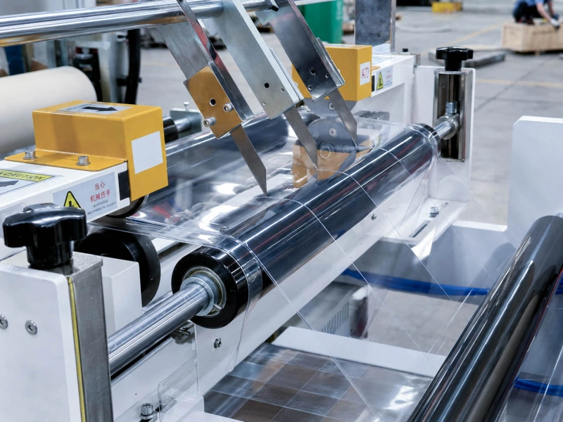
Roller positions used for film guiding, traction, tension contact, and rewinding.

Film may run normally and then break during acceleration. It may repeatedly tear from the same edge, fail in one narrow slit strip, or break near the same roller position. Changing the overall tension is rarely the best first step. A better starting point is to record where the tear began, when it happened, whether it followed the same knife, joint, strip, or roller position, and what changed immediately before the break.
These details usually show whether the problem started with the film, the cutting edge, a film joint, a short tension change, or contact with a roller. Rubber-covered rollers often pull the film, transfer speed, and keep contact stable during slitting and rewinding. A dirty surface, weak grip, sudden grabbing, or bearing resistance can therefore be part of the same break event and should be checked together with the material, knives, tension, and machine movement.
The place where the broken film is found may not be where the tear began. A small cut can start at one edge, continue across the film, and travel through several roller positions before the machine stops.
When it is safe to do so, keep the broken section and place the two ends together. Look for the first small notch, hole, scratch, fold, damaged slit edge, hard joint area, or mark left by adhesive or dirt. Mark the machine direction and strip number on the sample before restarting.
| Where the tear starts | What to check first |
|---|---|
| One film edge | Incoming edge damage, knife damage, side contact, or trim interference |
| The same narrow strip | Damage from one knife, a weak slit edge, or uneven winding load |
| Film center | A hole, thin area, coating defect, scratch, or trapped particle |
| Cutting section | Blade damage, buildup, unstable cutting, or a loose knife holder |
| After the same roller | Surface damage, dirt, turning resistance, weak grip, or sudden grabbing |
| Film joint | Weak joining, hard tape edge, adhesive contamination, or poor alignment |
The tear shape can add another clue. A long diagonal tear usually begins at one side. A small hole that opens into a larger tear normally points to local film damage. A sudden break across most of the width is more likely to follow a quick change in pulling force.
Narrow slit strips are more sensitive to edge damage because the remaining material has less width to carry the load. A small notch that causes little trouble on a wide web can become a serious weak point after the film is divided into narrow strips.
The timing of the break helps separate a continuous problem from a short machine event.
| When the film breaks | More likely direction |
|---|---|
| During steady running | Material weakness, knife damage, continuous roller resistance, or fixed surface damage |
| During acceleration | A roller or roll cannot speed up smoothly, grip becomes unstable, or a weak edge is pulled harder |
| During deceleration | Brake response, sudden tightening, or temporary loss of grip |
| Immediately after restart | Film sticking, static cling, a stiff joint, or poor release from a roller surface |
| At a similar roll size | A change in roll weight, motor load, or winding condition |
If reducing acceleration lowers the number of breaks, the line probably contains a position that cannot follow the speed change smoothly. The next step is to compare the unwind, rewind, brakes, motors, free-turning rollers, tension arms, and any rubber roller where the film appears to slide.
The tension value shown on the screen may still look normal. A very short rise can happen too quickly to appear clearly, or it may occur between the sensor and the actual break point. For this reason, the break time should be compared with line speed, tension movement, motor load, and the size of the unwind and rewind rolls.
When breaks repeatedly follow acceleration, deceleration, or changing roll diameter, the related tension control roller positions should be checked together with the drive and brake response.
Film can become easier to tear after coating, lamination, drying, curing, cooling, or storage. The material name and nominal thickness alone do not show whether one area has become weaker than the rest.
Compare the current roll with a roll that ran normally. Check untreated film against coated or laminated film, center material against edge material, and the broken strip against the strips beside it. If the break rate changes after curing, cooling, or storage, that process history should stay in the investigation.
Uneven coating, local overheating, poor drying, adhesive contamination, weak bonding between layers, or a local thin area can all create a starting point for the tear. A wide film may run successfully before slitting and still fail afterward because narrow strips expose small edge cuts and weak areas more clearly.
For wider thin-film contact and handling requirements, see film converting rollers. For the current break event, however, the retained sample and its production history are the better starting points.
A knife can damage the film even when the cut edge does not look obviously rough. A small chipped section, a worn blade, adhesive buildup, particles around the cutting point, unstable blade contact, or movement in the knife holder can create an intermittent weak edge.
Compare the broken strip with a neighboring strip cut by another knife. If the break moves when the knife position is changed, the cutting setup becomes the stronger lead. If it remains on the same physical side of the parent roll, the damage may already exist before the knife.
When the starting point moves sideways as the film moves sideways, the related web tracking problem should be checked. For this break investigation, the useful question is where that sideways movement first damages the film edge.
Film joints should be checked in the same practical way. Look at whether the two film ends are aligned, whether the tape is too thick or too hard, whether adhesive has squeezed outside the joint, and whether the joint catches a guide edge or narrow opening. The joint may fail directly, or it may remain intact but create a short pulling or contact change when it reaches a driven roller or pressure point.
After the film, knives, and joints have been checked, look at the section immediately before the tear started.
Rubber rollers commonly pull the film, transfer speed, and maintain contact. Guide rollers change the web path, while tension-related rollers help keep the film running with stable tightness. A problem at any of these positions can add extra pulling force to an edge that is already damaged.
A roller may appear normal at low speed but create resistance during acceleration. Bearing noise, extra heat, rough turning during a safe shutdown, dirt around the shaft, side movement, or a roller that stops much faster than similar rollers can all indicate that it is not turning freely.
At positions where the film changes direction, guide rollers should remain clean, parallel, and easy to turn. Resistance or poor alignment on one side can place more pulling force on one edge or narrow strip.
Film can also slide briefly on a rubber roller and then be caught again. This sudden grip may finish a tear that has already started at an edge, knife cut, or joint. Operators may hear a squealing sound, see movement between the film and roller, or notice a smooth and shiny band on the roller surface.
When these signs stay around the same position, inspect the traction roller, its rubber surface, and the way the film wraps around it. Adhesive, oil, dust, polishing, cuts, and uneven wear can all make grip less stable. The wider slipping problem is covered in why web materials slip on rubber rollers.
Static electricity can pull light film toward a roller, frame, knife holder, or waste-edge path. Before the break, the film may flutter, one edge may fold, or the film may begin to cling to and wrap around a surface.
The useful information is the exact position where this starts, the line speed, and the room conditions at the time. Cleaning, grounding, and static-control equipment should be checked before changing the general tension.
If static repeatedly affects the same film-contact roller, an anti-static or conductive rubber roller may be worth reviewing. Its use should match the actual grounding method and roller position rather than being treated as a stand-alone solution.
When repeated breaks occur around one rubber roller position, inspect the full roller rather than looking only at the rubber material name.
Use light from the side to check for cuts, dents, hard deposits, adhesive, dust, oil, smooth polished areas, and uneven wear across the roller width. Small raised deposits and shallow cuts can be difficult to see from directly above.
The bearing and roller movement also matter. Check whether the bearing is noisy or hot, whether the roller turns smoothly, whether it visibly wobbles, and whether it remains parallel to nearby rollers. Watch the film as it enters and leaves the contact point. It should move smoothly rather than slide, hesitate, or release suddenly.
If the original roller worked well for a long time and the problem appeared after surface damage or bearing wear, a straightforward replacement may be enough. If the same break returns after cleaning, grinding, or replacement, the review may need to include rubber hardness, surface finish, roller accuracy, bonding, and actual contact pressure.
For roller positions used on this type of equipment, see Slitting and Rewinding Line Rollers.
A roller change cannot repair a weak film joint, damaged knife edge, or brittle film area. The replacement direction should match the break pattern recorded on the line.
Several short records are usually more useful than one long inspection after the problem has changed.
| What to record | Details |
|---|---|
| Tear starting point | Left edge, right edge, center, narrow strip, knife, joint, or roller position |
| When it happened | Steady running, acceleration, deceleration, or restart |
| Film details | Film type, thickness, full width, and strip width |
| Machine condition | Speed, tension movement, and unwind or rewind roll size |
| Knife or joint | Knife number, recent adjustment, or joint details |
| Roller condition | Dirt, surface damage, slipping, resistance, heat, or wobble |
| Last change | Material, speed, tension, knife, cleaning, joint, or roller change |
Keep one close photo of the tear starting point and one wider photo showing the running direction and strip position. During a controlled test, change one condition at a time. Changing speed, tension, knife position, and cleaning method together makes the result difficult to understand.
For a repeated film break, send photos of both broken ends and a close photo of the starting point. Include the film running direction, strip number, material type, thickness, full width, and narrow-strip width. The speed stage, tension movement, knife or joint condition, coating and curing history, and any signs of sticking, slipping, static, roller resistance, or vibration are also useful.
When one roller position is involved, send the roller drawing or basic dimensions, roller diameter, rubber-covered face length, shaft and bearing details, film wrap direction, known rubber material and hardness, and photos of surface damage or uneven wear. It also helps to mention whether the roller was recently replaced, ground, or re-covered.
These details help separate a normal replacement from a repeated problem that needs a closer check of the rubber surface, bearings, grip, and roller accuracy.
Roller positions used for film guiding, traction, tension contact, and rewinding.
A wider guide to wrinkles, slipping, edge instability, and winding problems.
For breaks linked to changing speed, tension, or roll diameter.
For roller alignment, turning resistance, and film-path checks.
For unstable grip and sudden film catching.
For static-related sticking and unstable film contact.
Start with the tear location, break timing, film and strip width, knife or joint condition, and the roller position nearest to the event.
If you already have drawings, sizes, samples, or a clear specification, you can send them to us directly. We can proceed with custom manufacturing, quotation, or production confirmation based on your documents.
If the information is not complete yet, you can still start with the roller position, film type, contact condition, and repeated break pattern.