Why Does Coating Thickness Vary Across the Web?

Uneven coating can show up in several ways. The center may be heavier than the edges. One side may carry more coating than the other. A narrow strip may stay too thin, or the coat weight may slowly change as the line keeps running.

These patterns rarely come from exactly the same source.

Before changing settings, check how the thickness is changing. Is the difference across the web, along the running direction, or repeating at a regular distance? Does it stay stable, or does it move after the coating warms up, the speed changes, or the line runs for longer?

That first check helps separate fluid delivery, viscosity, coating-head setup, web condition, and roller-related causes.

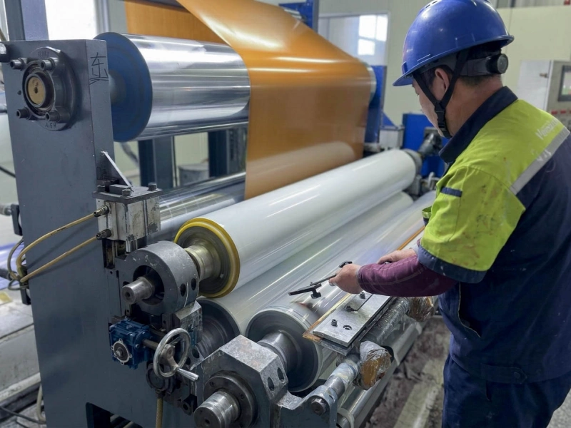
Worker adjusting a white rubber roller on a film laminating line

First Check How the Thickness Is Changing

An average coat-weight result can look acceptable while part of the web is still too light or too heavy. Measure the same positions from the operator side to the drive side, then repeat the measurement later in the run.

What you see Main areas to check
Center heavier than the edges Flow distribution, coating-head loading, roll bending, gap shape, and web support
One side heavier Side-to-side supply, web tension, pressure distribution, roll parallelism, and one-sided wear
One narrow thin or thick zone Local blockage, blade damage, particles, substrate variation, or local roller contamination
Whole profile rises or falls Flow, viscosity, temperature, web speed, and overall metering
Thick and thin areas repeat Rotating rolls, pump cycles, runout, eccentricity, or local surface damage
Coat weight slowly drifts Fluid warming, evaporation, tank condition, filters, speed relationship, or thermal movement

Two patterns can happen at the same time. One side may remain heavy while the overall coat weight slowly falls. In that case, the cross-web profile and the time-related change should be treated as separate clues.

What the Cross-Web Profile Can Tell You

When the Center Is Heavier

A center-heavy profile means the middle of the web is seeing a different coating or contact condition from the edges.

The coating head may be feeding more material toward the center. Blade or die loading may differ across the width. A roll may bend slightly under working pressure, changing the effective gap between the center and the edges. Edge curl or weak support can also reduce contact near both sides.

Roll wear can create a similar result. After long use or repeated grinding, the center may have a different diameter or surface condition from the edges.

A useful check is to change the overall coating amount without changing the width-direction setup. If the center-heavy shape remains, the source is more likely connected to coating distribution, web support, or roll geometry.

When One Side Is Heavier

A one-side-heavy profile usually shows that something is different between the operator side and the drive side.

The difference may begin in the fluid system. One side may receive more coating because of uneven supply pressure, edge settings, restricted flow, or coating-head loading.

The web can also enter the coating point differently on each side because of tension, curl, tracking, or substrate thickness.

On the mechanical side, small differences in roll parallelism, bearing position, cylinder load, shaft alignment, or roll diameter can create a clear coat-weight slope across a wide web.

The response to adjustment gives the best clue. If the heavy side changes directly after a gap or pressure adjustment, the contact geometry deserves closer attention. If it follows tank level, fluid temperature, pump condition, or coating batch, the fluid side remains the better starting point.

When One Narrow Zone Is Wrong

A narrow thin or heavy strip is usually caused by a local condition.

The first places to inspect are the flow path, blade edge, coating head, substrate, and roller surface at the same width position. Dried coating, particles, a damaged blade, a local substrate difference, or a worn strip on a roll can all create a narrow abnormal zone.

Find the first station where the thickness difference becomes measurable. If the same strip always appears after one coating or transfer point, inspect that position before changing settings elsewhere.

A local roller problem often leaves visible evidence at the same position, such as coating build-up, a polished strip, different surface texture, or unusual wear.

If the main problem is a visible scratch, line, or pressure mark rather than a measured coating-thickness difference, see coating line surface marks.

When Coat Weight Changes During the Run

A coating profile can look good at start-up and move after the line has been running for some time.

The fluid may become warmer and change viscosity. Solvent or water may evaporate. The tank level may fall, a filter may start restricting flow, or mixing may become less even. The web and machine may also behave differently after reaching a stable operating temperature.

Look at how the change spreads across the web.

If every measurement position rises or falls by a similar amount, the likely area is total flow, viscosity, temperature, web speed, or overall metering.

If one side changes more than the other, the width-direction supply and contact condition still need attention.

The production record should describe when the change begins. “The coating changes after running for a while” gives little direction. “The drive side becomes heavier after the fluid reaches operating temperature” is much easier to investigate.

What a Speed Change Can Reveal

A speed change can expose a process that was already close to an unstable condition.

If the whole profile rises or falls after the line speed changes, compare the coating delivery with the new web speed. The pump setting, actual flow, viscosity, and overall metering condition may no longer match the faster or slower line.

In roll coating, the actual surface speeds of the applicator, metering, and transfer rolls also affect how much liquid is carried and transferred. A speed change can alter the coat weight even when the mechanical gap has not been adjusted.

If the average coat weight changes and the cross-web shape changes at the same time, check the roll-speed relationship together with the gap, web support, and roll parallelism.

Direct roll coating, reverse roll coating, and slot-die coating do not control coating amount in the same way. A gap or speed ratio that works on one system should not be copied directly to another.

Check the Fluid, Coating Head, and Web First

Before moving directly to the rollers, confirm that the coating supply is stable.

Pump output, tank level, filter condition, mixing, restricted flow paths, and side-to-side distribution can all change the amount of coating reaching the application point. Viscosity and temperature should be recorded at the same time as the thickness profile. A value taken before start-up may no longer represent the fluid later in the run.

The coating head also needs a close look. Dried coating, particles, blade damage, uneven loading, or different edge settings can all affect the cross-web profile. The relevant checks depend on the coating method, so the inspection should follow the actual machine rather than a general coating rule.

The web must enter the coating point in a stable condition. Tension, tracking, curl, wrinkles, substrate thickness, splices, and web support can change how the material meets the coating head and rolls.

Once these conditions are reasonably stable, any remaining profile change that follows gap, pressure, roll speed, cleaning, or rotation becomes much more useful evidence for a roller check.

Signs That Point Back to the Rolls

In roll-coating systems, the applicator roll and the metering roller help control the liquid film through their gap, surface speed, and contact condition.

These rolls should be checked more closely when the coating changes after a gap adjustment, roll-speed change, grinding, roller replacement, bearing work, or remounting.

Use actual operating speeds rather than only the percentages shown on the control panel. Also check the gap at both ends. A setting that looks correct on the operator side may still be different on the drive side.

Pressure distribution matters as well. A pressure roller may not meter the coating directly, but it can change web support and loading. On a wide web, a small difference in cylinder load, bearing position, roll diameter, or roll bending can produce a visible coat-weight slope.

If the profile changed soon after roller work, compare the current roller with the previous condition. Diameter profile, mounting, bearing condition, surface finish, and runout are more useful than simply asking whether the roll is new.

The Roller Surface Can Change the Coating Profile

A roller can be correctly installed and still produce uneven coating if the surface is no longer uniform.

Dried coating, adhesive build-up, glazed areas, cuts, dents, or a worn strip can change how much liquid the surface carries and releases. A local deposit may create a heavy zone. A polished or worn area may transfer less coating.

Where coating passes through several roller contacts, inspect the transfer rollertogether with the metering and applicator rolls. The problem may begin on one roller surface and only become visible after the next transfer point.

Cleaning can also provide a useful clue. If one local zone improves immediately after the roller is cleaned and returns when residue builds again, the surface condition is likely involved.

If the rubber surface remains sticky or residue returns quickly, see material sticking to rubber roller surfaces.

When the Rubber Cover Needs a Closer Look

For rubber-covered metering, transfer, or pressure rolls, the cover condition can affect the coating profile even when the roller still looks acceptable from a distance.

The rubber may become harder on one side, softer in another area, or more worn through the center. Contact with coating, solvent, or cleaning liquid may cause swelling or surface change. Grinding may also leave a different diameter profile or finish from one side to the other.

These changes can affect the working gap, pressure response, liquid transfer, and release from the roller surface.

Two rubber covers can use the same general material name and still behave differently. The rubber compound, hardness, bonding, curing, grinding, and surface finish all affect how the roller performs under real coating conditions.

For a normal replacement, the existing drawing, dimensions, hardness, roller position, and old roller photos may be enough to start.

When the same profile problem returns after re-covering or replacement, repeating the old specification without checking the actual contact medium and operating condition may repeat the same result.

When the Thickness Pattern Repeats

If thick and thin areas return at a regular distance, compare that distance with the circumference of the rolls in the coating section.

Runout, eccentric rotation, bearing movement, local surface damage, or contamination can make the working gap change once per revolution. The relevant roll may be the metering roll, applicator roll, transfer roll, or a supporting pressure roll.

Also compare the repeat frequency with roller speed. If the spacing changes when the roll speed changes, that gives the maintenance team a clearer position to inspect.

A matching repeat distance does not prove that the roll is the only cause, but it is much stronger evidence than a general guess.

For more detail on this mechanical direction, see roller runout, misalignment and eccentricity.
What to Record

Before checking or replacing a roller, record:

  • Wet thickness, dry thickness, or coat weight at fixed cross-web positions
  • Web width and substrate information
  • Line speed, web tension, fluid viscosity, and temperature
  • Metering-, applicator-, and transfer-roll speeds
  • Gap or pressure setting
  • When the variation begins and whether it repeats
  • Visible roller wear, swelling, glazing, or contamination
  • Recent grinding, bearing work, roller replacement, or remounting

Use the same measurement positions and the same process stage each time. Wet thickness, dry thickness, and coat weight should be recorded separately.

For a wider view of roller positions around coating and laminating equipment, see coating and laminating line rollers.

Send Drawings or Roller Details

If the coating profile points to a metering, transfer, applicator, or pressure roll, send the roller drawing, dimensions, hardness, surface requirement, old roller photos, and the problem seen on the line.

Wolorin can support drawing-based replacement, sample-based manufacturing, selected re-covering, quotation, and production confirmation through our industrial rubber roller services.

If you already have drawings, sizes, samples, or a clear specification, you can send them directly.

If the information is not complete yet, start with the roller position, coating method, contact medium, and the thickness problem you are seeing.