
Gravure ESA Impression Roll Problems

Weak electrostatic assist often appears first as a printing change. Fine image areas develop more missing dots, one band across the web transfers less cleanly, or the improvement normally seen with ESA on becomes noticeably smaller.

Arcing and changing resistance give stronger location clues. Pay particular attention when either starts after the impression roll has been ground, worn down, re-covered, or replaced.

A few comparisons usually narrow the direction quickly: Does the print change when ESA is switched on and off? Does a weak area stay at the same position across the roller face? Does an arcing point follow the roller as it turns, or stay fixed on the machine?

ESA helps ink transfer from the gravure cells at the print nip. Missing dots can also come from blocked cells, ink condition, substrate contact, or mechanical impression. If the defect changes very little with ESA on and off, continue with the broader gravure missing dots and ink transfer checks.

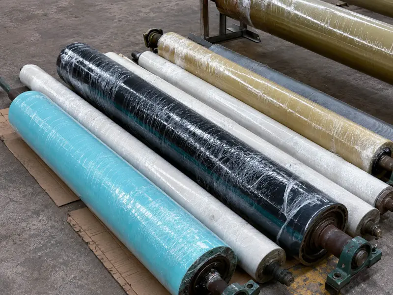
lote surtido de rodillos de caucho

Where Problems Can Develop Along the ESA Path

A practical check follows the electrical path through the printing unit:

ESA charging system → roller core or sleeve → conductive or semi-conductive cover structure → working surface → substrate → gravure cylinder

The impression roll sits in the middle of this path and carries the mechanical impression load at the same time. Poor nip contact can weaken transfer even when the electrical side is working correctly. An unsuitable roller construction can also limit ESA performance even when the mechanical impression looks normal.

ESA equipment uses different charging arrangements. Depending on the press and system, the electrical route can involve the core, carrier sleeve, insulating sections, conductive or semi-conductive layers, and the outer working cover in different ways.

General conductive material directions can be found under Rodillos de caucho antiestáticos/conductores. For an ESA impression position, use the press or ESA supplier's roller specification and approved measurement method as the reference.

High-voltage components, electrodes, grounding, electrical connections, and ESA safety circuits should be checked by qualified press or ESA personnel.

Keep a Baseline Before Changing Several Conditions

ESA troubleshooting becomes much easier when measurements taken weeks or months apart can actually be compared.

Record Details Worth Keeping
Sistema ESA Equipment supplier, system type, and specified roller electrical requirements
Electrical measurement Instrument, approved method, measurement position, date, roller temperature, and humidity
Condición del rodillo Original and current diameter, remaining cover thickness, grinding and re-covering history
Printing condition Substrate, line speed, impression setting, and recent process changes
Visible problem Cross-web position, arcing location, cracks, burn traces, contamination, or unusual wear
ESA comparison Result from the same marked print area with ESA on and off

The useful part is the sequence: when the roller worked normally, what changed, and when the symptom first appeared.

What Weak ESA Looks Like on Press

Start with the same print area under comparable conditions. Keep the substrate, ink condition, line speed, and impression setting as stable as practical, then compare ESA on and off.

If transfer improves clearly with ESA on and falls back when it is switched off, the electrostatic assist is contributing to the result. If this difference used to be clear and has gradually become much smaller, look at what changed during the same period.

A recent roller replacement, grinding cycle, increasing cover wear, substrate change, different humidity, or work on the ESA equipment can all provide useful timing clues.

Mechanical impression still needs to be separated from the ESA effect. When the defect responds strongly to pressure adjustment but changes little with ESA on and off, check roller profile, surface condition, hardness, runout, and pressure distribution. These factors are covered further under Rodillos de presión.

A Fixed Weak Band Can Help Locate the Problem

A general complaint that “ESA is weak” gives little location information. A narrow weak band that keeps returning in the same place is far more useful.

Mark the band across the substrate and compare it with the corresponding area on the impression roll face. If the weak zone remains in the same position through different images or production jobs, inspect that section of the roller for uneven wear, contamination, cuts, cracks, or other surface changes.

For example, a wide gravure job may print normally across most of the web while one lane near an edge repeatedly loses ESA benefit. If the weak lane stays in that position even after the image layout changes, the location itself becomes an important clue.

When the weak area consistently follows one roller-face zone, the impression roll deserves closer inspection. When it stays tied to a charging zone or another fixed part of the machine, the ESA equipment side deserves more attention.

Arcing Can Reveal Whether the Fault Moves With the Roller

Before cleaning the area or changing parts, record where the discharge appears.

From the roller side, useful visible evidence includes small cuts, cracks, pinholes, worn edges, contamination tracks, burn marks, or an underlying layer becoming visible through the cover.

Watch what happens over several roller revolutions.

If the discharge returns whenever the same circumferential point reaches the nip or charging area, inspect that physical point on the roller closely. A small damaged area can produce a once-per-revolution event and appear intermittent on press.

If the discharge remains at the same machine-side position while different parts of the roller pass through it, the evidence points more strongly toward a stationary electrode, nearby electrical component, or another fixed part of the ESA path.

Ink mist, solvent residue, cleaner residue, and contamination around a damaged surface can make the local condition less stable. If arcing keeps returning, photograph the surface before it is cleaned again.

Resistance Drift Only Makes Sense as a Trend

A single resistance reading has limited value without the measurement conditions around it.

Use the same approved method and measurement position when comparing the roller over time. Keep the instrument type, roller temperature, humidity, current diameter, and surface condition with the reading.

ESA impression rolls may contain several electrically functional sections. Depending on the design, the supplier can define different electrical properties for different parts of the roller construction. A convenient value measured at the working surface may therefore represent only one part of the electrical path.

If the specified test requires a particular measurement arrangement, keep using that arrangement for comparison. Changing the method halfway through the roller's service life can create an apparent “drift” that comes from the test rather than the roller.

The most useful history often looks simple: the roller was stable at its earlier diameter, went through several grinding cycles, and then the electrical readings or print behavior began to move.

Why Grinding History Matters on an ESA Roll

Every grinding cycle removes part of the rubber cover and moves the working surface closer to the structure underneath.

On a multi-layer ESA roll, this can reduce the remaining thickness of a functional layer, move the surface closer to a transition between layers, or bring previously buried damage closer to the working surface.

The electrical result depends on the actual construction. There is no useful universal rule saying that resistance must rise or fall as the roll becomes smaller.

For a roller that has been ground several times, keep the original diameter if known, current diameter, remaining cover thickness, grinding dates or history, and comparable electrical readings. This makes it possible to see whether the change developed gradually with cover removal or appeared suddenly after one grinding operation.

Grinding also changes the working surface. If weak transfer or unstable behavior starts immediately afterward, check surface condition, roller geometry, and the electrical history together.

What Can Change After Re-Covering or Roller Replacement

A re-covered ESA impression roll can match the drawing in outside diameter, face length, and hardness and still behave differently on press.

The finished roller may depend on the relationship between the core or carrier sleeve, insulating section, conductive or semi-conductive layers, working cover, and the connections between those sections.

Cover thickness, bonding, curing, grinding, and final surface condition all become part of the finished build. A replacement that copies only diameter, hardness, and a general rubber name can miss part of the original ESA construction.

This becomes especially relevant when the old roll worked normally for a long time and weak ESA, resistance drift, or arcing begins immediately after re-covering or replacement.

Keep the previous drawing, original roller specification, old electrical records, grinding history, and photos of the old cover when available. They give a much clearer manufacturing reference than the material name alone.

Two covers described under the same general rubber family can still behave differently because of compound direction, conductive structure, bonding, curing, layer build, grinding, and finished surface condition.

What to Prepare for an ESA Impression Roll Replacement

When an existing ESA impression roll has worked well for a long time, a confirmed drawing and proven specification can make replacement straightforward.

If the old roller has developed weak assist, resistance changes, arcing, cracking, or unusual wear, include the history that shows what happened to the roller over time.

La información útil incluye:

  • Roller drawing or the main dimensions.
  • Outside diameter, face length, shaft or sleeve details.
  • Old roller photos, especially cracks, burn traces, wear, contamination, or edge damage.
  • Roller position and printing unit.
  • ESA system and supplier information, together with the specified roller requirements when available.
  • Cover material, hardness, original thickness, current remaining thickness, and grinding history when known.
  • Ink, solvent, cleaner, or other media that contact the roller cover.
  • The current roller-related problem and when it started.
  • Whether the symptom changes with ESA on/off, roller position, grinding, speed, humidity, or roller temperature.

These details help separate a straightforward reproduction of a proven roller from a replacement that needs closer confirmation of the cover and electrical construction before manufacturing.

Problems traced to the generator, electrodes, grounding, high-voltage circuit, or other ESA hardware should remain with the press or ESA equipment specialist. Roller manufacturing becomes relevant when the evidence points to the impression roll construction, cover condition, wear history, or replacement itself.

For other rubber-covered positions around the press, Rodillos para la industria de la impresión provides the wider application context.

Rodillos de caucho antiestáticos/conductores — Conductive and charge-control material directions for industrial rubber rollers.

Rodillos para la industria de la impresión — Rubber-covered roller positions used around printing and material handling.

Rodillos de presión — Mechanical nip contact, pressure distribution, roller geometry, and surface condition.

Rodillos de caucho NBR/nitrilo — General NBR material information for selected ink and industrial media-contact roller positions.

If you already have drawings, dimensions, samples, or a clear ESA impression-roll specification, send them directly for custom manufacturing, quotation, or production confirmation.

If details are incomplete, start with old roller photos, basic dimensions, roller position, contact medium, and the current roller-related problem.